
Under the same process parameters, three sand casting schemes were numerically simulated (Fig. 1). It can be seen from the casting liquid filling process of sand casting that the whole filling process is relatively stable, and there is no splashing impact of casting liquid.
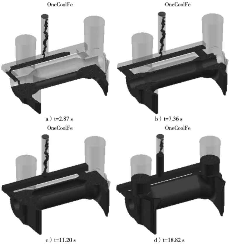
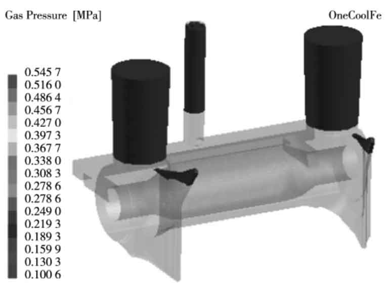
Figure 2 shows the gas distribution in the unfilled cavity area at a certain time (indicated by the dark part). It can be seen from Figure 2 that there is gas at the ear of sand casting that cannot be discharged, so there is a risk of insufficient filling in this part. In actual production, air outlet or air needle shall be set at this place.
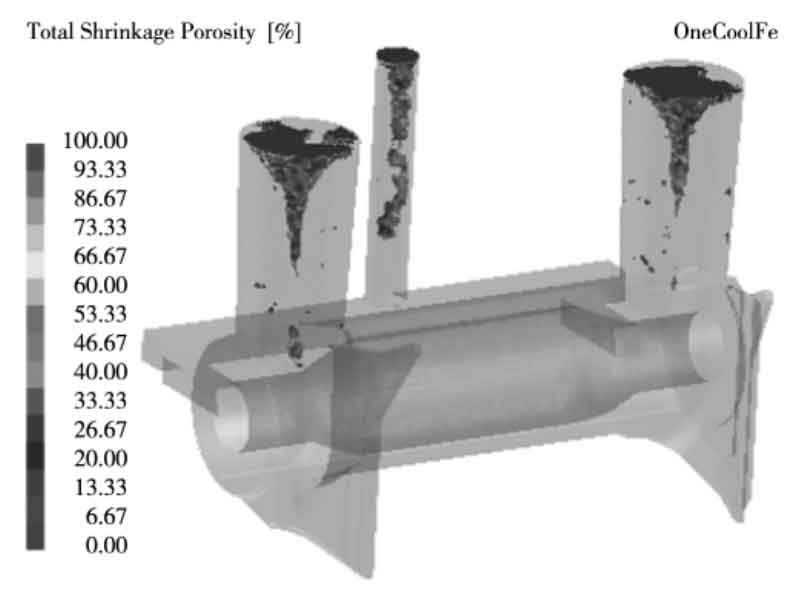
According to the prediction diagram of shrinkage cavity, shrinkage cavity is mainly distributed in the middle and upper part of the riser, and a small amount is seen
At the bottom of the riser, there is no shrinkage cavity distribution on the sand casting (Fig. 3).
See Table 1 for the simulation results of the three schemes. Among them, the chilling effect of cold iron in scheme 1 is significant, and the average curing rate at the end of mold filling is 15.1%, which is higher than that of the other two schemes, indicating that the fluidity of cast steel liquid decreases and the feeding capacity of riser becomes worse during mold filling, which may lead to the risk of dissatisfaction at the highest part of the ear; In scheme 2, after the size of cold iron is reduced and the placement position is improved, the curing rate at the end of mold filling is 11.3%, which ensures the subsequent filling effect. Although the maximum temperature of cold iron surface reaches 1257 ℃, it is still lower than the solidus temperature 1493 ℃ of Q235, and there will be no phenomenon that cold iron melts and is cast and welded on sand castings; In scheme 3, the filling time without cold iron, the curing rate at the end of mold filling and the solidification time of sand casting are basically close to that in scheme 2, but the surface temperature of the sand core reaches the maximum 1594.7 ℃ when it solidifies to 32%. Due to the characteristics of high-temperature collapse of the carbon dioxide hardened sodium silicate silica sand material used in the sand core, it is easy to have the defect of sand sticking in the shaft hole.
| Project | Option 1: silica sand casting core / one cold iron | Option 2: silica sand casting core / two cold irons | Option 3:Silica sand core / no cold iron |
| Process time / S | 5208 | 5344 | 5386 |
| Filling time / S | 25.00 | 25.00 | 24.14 |
| Average curing at the end of filling /% | 14.9 | 10.9 | 11.2 |
| Complete setting time / S | 4918 | 5020 | 5041 |
| Maximum temperature of chilled iron surface / ℃ | 1164.3(solidification 86%) | 1248.0(solidification 76%) | — |
| Maximum surface temperature of sand core / ℃ | 1421.0(solidification 84%) | 1420.0(solidification 86%) | (solidification 33%) |
The hot tearing indicator (HTI) provided by the numerical simulation software ProCAST is used to predict the location of hot crack risk of sand castings when the local curing rate reaches 99%, as shown in Figure 4.
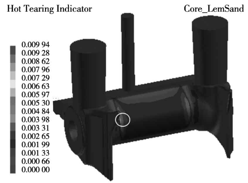
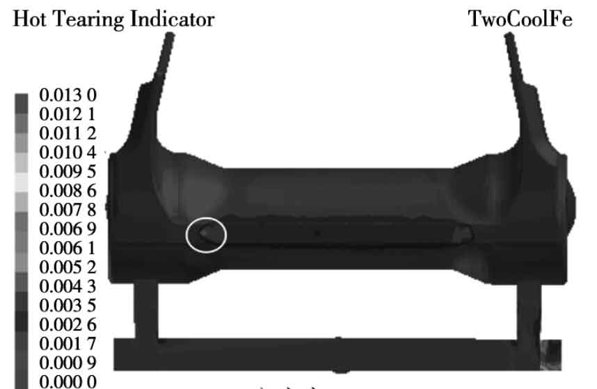
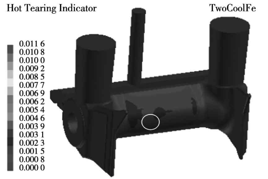
Collect hit data in areas prone to thermal cracks, as shown in Table 2. It can be seen from table 2 that the hit is the largest when one cold iron is set, and the hit is very close when two cold iron or no cold iron is set. Therefore, the sand casting scheme with one cold iron has the greatest risk of hot crack, and the risk of hot crack is basically the same with and without two cold irons. It can be seen from the partial stress data that the tensile stress in the Y direction (parallel to the axial direction) is the largest, and the resulting crack will expand perpendicular to the axial direction, which is consistent with the crack shape formed in actual production.
| Project | A cold iron | The cold iron | No cold iron |
| HTI | 0.004 2 | 0.002 9 | 0.003 0 |
| Average stress / kPa | 0.230 | 0.200 | 0.210 |
| Stress in X direction / kPa | 0.029 | 0.006 | 0.002 |
| Stress in Y direction / kPa | 0.316 | 0.150 | 0.222 |
| Stress in Z direction / kPa | 0.019 | 0.025 | 0.012 |
Based on the above analysis, the risk of hot crack in scheme 2 is the smallest, but the chilling effect of cold iron is easy to cause air holes in sand castings in actual production. In addition, in order to prevent the formation of cold iron gap crack, the cold iron is required to be placed at a reasonable angle, which increases the difficulty of sand mold making. Although the risk of hot cracking in scheme 3 is slightly higher than that in scheme 2, the use of cold iron is reduced and the risk of porosity defects in sand castings is reduced; Due to the sand sticking problem caused by the high-temperature collapse of the sand core material in the shaft hole, the material for making the sand core can be replaced with carbon dioxide hardened water glass limestone with better thermal conductivity. Through simulation and comparison, after replacing the sand core material with limestone sand, the risk of thermal cracking is smaller than that of scheme 2 (Table 3)
| Project | Silica sand core / no cold iron | Limestone sand core / no cold iron |
| HTI | 0.003 0 | 0.002 7 |
| Average stress / kPa | 0.211 | 0.179 |
| Stress in X direction / kPa | 0.002 | 0.007 |
| Stress in Y direction / kPa | 0.223 | 0.185 |
| Stress in Z direction / kPa | 0.012 | 0.013 |