
1. Part Structure and Material Analysis
| Analysis Aspect | Details |
|---|---|
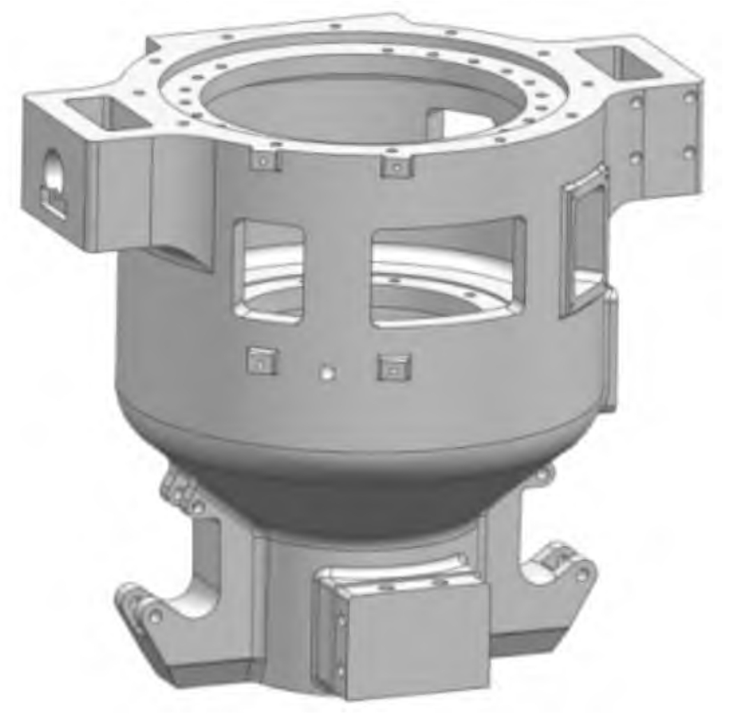
| Part Structure | Outer contour size: 1040 mm×760 mm×933 mm, material: ZG25CrNiMo, density: 7.85 g/cm³, maximum wall thickness: about 187 mm, minimum wall thickness: 45 mm, small end wall thickness is thicker, large end wall thickness is uniform without large hot spots |
| Part Material | ZG25CrNiMo, good toughness, high tensile strength, excellent fatigue resistance, chemical composition: C (0.22 – 0.30), Si (0.30 – 0.60), Mn (0.7 – 1.00), Cr (0.60 – 0.90), Ni (0.60 – 1.10), Mo (0.35 – 0.50), Fe (balance) |
2. Pouring Position and Parting Surface Selection
| Scheme | Advantages | Disadvantages | Selection Result |
|---|---|---|---|
| Scheme 1 | Casting is all placed in the lower mold, good size accuracy; vertical sand core positioning is accurate; two – box horizontal parting, convenient for manual molding | Inconvenient for mold removal, need to add more loose pieces or sand cores | Not selected |
| Scheme 2 | Casting is all located in the upper mold, has the advantages of Scheme 1, and only needs to add a small number of loose pieces or sand cores, convenient for mold removal | – | Selected |
3. Pouring System Design
3.1 Pouring System Design Scheme
| Pouring System | Characteristics |
|---|---|
| Bottom Pouring System | Upper mold height is more than 1 m, for convenience of molding, use ceramic tube straight runner and wooden mold transverse runner and multiple parallel internal runners to avoid heat concentration near the internal runner |
| Top Pouring System | To ensure higher temperature at the upper part of the casting and make sequential solidification more obvious, all use ceramic tube pouring system |
3.2 Determination of the Cross – sectional Areas of the Two Pouring Systems
| Pouring System | Package Hole Diameter (∑A包) | Straight Runner | Transverse Runner | Internal Runner |
|---|---|---|---|---|
| Bottom Pouring System | 50 mm (19.6cm^2) | 70 mm | 39.2cm^2 (bidirectional, each side 19.6cm^2) | 6 runners, each with an average cross – sectional area of 7.2cm^2, total ∑A内=43.1cm^2 |
| Top Pouring System | 50 mm (19.6cm^2) | 70 mm | 39.2cm^2 (bidirectional, each side 19.6cm^2, using 50 mm diameter ceramic tube) | 2 runners, each with an average cross – sectional area of 21.6cm^2, using 55 mm diameter ceramic tube, total ∑A内=43.1cm^2 |
4. Numerical Simulation Results and Analysis
4.1 Simulation Pre – processing
| Parameter | Value |
|---|---|
| Software | NX1847 for 3D model establishment, ProCAST for simulation |
| Pouring Temperature | 1550 °C |
| Pouring Time | 40 s |
| Sand Mold | Alkaline phenolic resin sand, silica sand as raw sand, heat exchange coefficient between metal and sand: 500W/(m^2•K) |
| Mesh Number | Bottom pouring system (Scheme 1): 1160633; top pouring system (Scheme 2): 897227 |
4.2 Filling and Defect Analysis
| Scheme | Filling Characteristics | Defect Situation |
|---|---|---|
| Scheme 1 (Bottom Pouring) | Filling is stable and orderly | Shrinkage porosity in the lower part is similar to Scheme 2, overall defect distribution is more even |
| Scheme 2 (Top Pouring) | Large drop during filling, metal liquid splashes, impacts the sand core easily causing sand drop | Less shrinkage porosity in the upper part, but overall defect distribution is not as good as Scheme 1 considering the impact on the sand core |
4.3 Selection of the Pouring System
- Scheme 2 has fewer defects in the upper part of the casting, but the lower part is the same as Scheme 1. Moreover, the filling is unstable and damages the sand core easily.
- Therefore, Scheme 1 (bottom pouring system) is selected for further process optimization.
4.4 Initial Optimization Measures
- Add a riser to the casting pouring system for feeding. Since the lower part of the casting is structurally constrained and a non – machining surface, it is inconvenient to set a riser. The riser is placed in the upper part where shrinkage porosity occurs.
5. Riser Design
5.1 Riser Type and Shape Selection
- Use a heating riser sleeve for better feeding effect and convenience in molding (left in the mold after molding). The riser is set as a circular open riser.
- Only one large riser is needed considering the maximum wall thickness at the upper end of the casting, its structural size, and feeding distance.
- Riser design and calculation using the modulus method:
- Calculate the modulus of the part requiring feeding: Mc=V/A. Measured volume V=38582915.9156mm^3, heat dissipation area A=663611.2742mm^2 (excluding the bottom non – heat dissipation surface), so Mc=5.8cm.
- Calculate the riser modulus: MR=f•MC, where f=1.2 (for open riser), so MR=7.0cm.
- Calculate the modulus of the heating and insulating riser: MRH = MR/1.43=4.9cm.
- Select a cylindrical heating and insulating riser with a diameter of 300 mm and a height of 300 mm. Its modulus is 5.0 cm, which is greater than the calculated value, meeting the requirements.
- Calculate the volume of the casting fed by the riser: VF=2/3VRH. The volume of the riser VRH=21.20dm^3, so VF=11.4dm^3. The volume of the casting is 163.1dm^3, and the volumetric shrinkage rate of the metal liquid ε=6.13%. The solidification volumetric shrinkage of the casting VS=163.1✖6.13%=10.0dm^3. Since VF>VS, the riser can meet the feeding requirements.
5.2 Initial Optimization Results Analysis and Summary
5.2.1 Simulation Pre – processing
- Import the 3D model with the added heating and insulating riser and air vents into ProCAST for simulation analysis. The 1# large sand core is a hollow sand core, and the air inside during pouring (including the heating riser sleeve, hollow sand core, and lifting lug sand core).
5.2.2 Solid Phase Fraction Analysis
- From the ProCAST solid phase fraction analysis:
- The lower part of the casting on both sides has a slower solidification rate due to thicker walls, resulting in isolated liquid regions.
- The middle part of the casting also has a relatively small isolated liquid region.
- The casting solidifies from the bottom to the top, and the riser solidifies last, which conforms to the sequential solidification principle.
- The heating riser cools the slowest, and a long calculation time is required. However, as long as the casting is fully solidified, the completion of the riser calculation does not affect the simulation result judgment.
5.2.3 Defect Analysis
- After the first optimization, defect simulation and analysis show that shrinkage porosity defects occur in the three isolated liquid regions identified in the solid phase fraction analysis. These defects are located in three positions of the casting where the wall thickness is relatively thick, forming small hot spots. Therefore, it is necessary to accelerate the cooling rate in these three positions to avoid heat concentration. Additionally, considering the overall heat dissipation of the sand mold, the middle sand core can discharge heat faster.
5.2.4 Secondary Optimization Measures
- To minimize the possibility of shrinkage porosity, the following improvements are made to the casting process:
- Set chills at the three defect positions of the casting to accelerate the cooling rate and avoid shrinkage porosity defects.
- Add vents in the lower mold and connect them to the hollow position of the 1# large sand core to accelerate the heat dissipation inside the casting, increase the cooling rate at the lower part of the casting, and improve the feeding effect of the upper riser.
6. Chill Design
6.1 Chill Position and Shape Selection
- Use external chills to eliminate local stresses in the casting, increase the feeding distance of the riser, and prevent cracks. The chill material is high – carbon steel.
- Set chills at the three isolated hot spot positions identified by the simulation analysis. The chills are placed on the outer plane and inner arc surface of the casting. The chills on the outer plane are formed chills, and those on the inner arc surface are special – shaped chills .
6.2 Secondary Optimization Results Analysis
- After adding chills and vents to the casting model and conducting the third simulation analysis and verification , the simulation results show that there are no visible characteristic defects inside the casting. This indicates that the improvement measures of setting chills and adding vents to enhance the internal heat dissipation of the casting are effective, and the casting process after the second optimization meets the predetermined requirements.
7. Conclusion
- Two pouring systems, top and bottom gating systems, are designed according to the structure and size characteristics of the casting.
- The bottom gating system is selected based on the ProCAST comparative simulation analysis of casting defects, and process optimizations are carried out twice by adding a heating riser, external chills, and vents successively.
- The numerical simulation analysis of the optimized casting shows that the solid phase fraction result indicates no obvious casting defects, and the casting achieves sequential solidification. This process improves the forming efficiency of the casting and ensures the casting quality.