
In my experience as a casting engineer, the production of high-integrity casting parts for transportation systems, such as subway axle boxes, presents significant challenges due to stringent quality requirements and complex geometries. These casting parts are essential for safety and performance, demanding meticulous process design to minimize defects. Here, I delve into the optimization of casting processes for such components, focusing on a case study of a subway axle box body. Through this first-person account, I aim to share insights into how systematic adjustments can enhance the quality of casting parts, leveraging tables and formulas for clarity. The keyword ‘casting parts’ will be frequently emphasized to underscore their importance in manufacturing.
The subway axle box body is a critical casting part in the bogie system, characterized by a symmetrical yet intricate design. Made from ZG230-450 steel, this casting part has a net weight of 45 kg and overall dimensions of 700 mm × 350 mm × 170 mm, with a primary wall thickness of 16 mm. Its structure features numerous intersecting ribs, classifying it as a thin-walled, multi-hot-spot casting part. Technical specifications mandate compliance with standards like TB/T 2942.1-2020, requiring dense internal integrity and surface finishes. Such casting parts must withstand high loads and speeds, making defect-free production paramount. Below, I outline the initial casting process, its shortcomings, and the optimized approach that significantly improved outcomes.
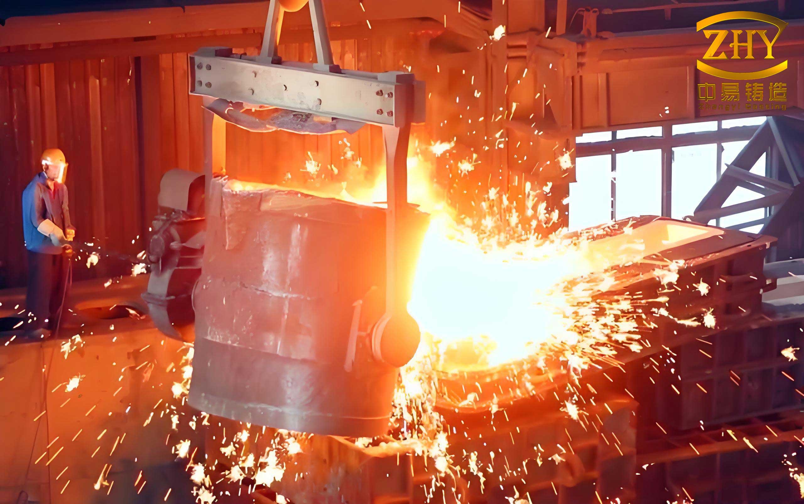
Initially, the casting process for these casting parts involved a two-piece pattern per mold with a symmetrical layout and a bottom-gating system. The gating system was designed with a pouring basin hole of 50 mm diameter, a sprue of 60 mm diameter, runner cross-sections of 65 mm/60 mm × 30 mm (trapezoidal), and ingates of 45 mm/40 mm tapering to 10 mm over 30 mm height. Steel entered at the rib positions to reduce erosion. Insulated sleeve risers were placed at central and side hot spots, with chills and nails used at minor hot spots to ensure denseness. The mold utilized CO2-cured sodium silicate sand, with chromite sand in critical areas. A machining allowance of 8 mm was on the top surface, and 5-6 mm elsewhere. This setup aimed to produce sound casting parts, but defects emerged, prompting my analysis.
During production, I observed two primary defects in these casting parts: blowholes on the inner surface of the axial cylinder and shrinkage porosity within the cylinder. The blowholes, 3-5 mm in size, were scattered in the upper regions, with spherical or elliptical shapes and dark, smooth walls. Based on visual inspection, I identified these as entrained air pores caused by improper gating design. Specifically, the sprue diameter (60 mm) exceeded the pouring basin hole (50 mm), leading to incomplete filling and air entrainment during pouring. The thin walls accelerated solidification, trapping bubbles. This issue highlighted how gating parameters directly affect the quality of casting parts. The shrinkage porosity occurred between risers and at fillet junctions, indicating inadequate feeding. The original crescent-shaped risers had a 15 mm thick and 80 mm deep wash, insufficient for effective feeding distance, resulting in centerline shrinkage in these casting parts. To quantify this, I considered the feeding range formula for casting parts:
$$L_f = \frac{4.5 \cdot M_r}{\sqrt{\rho}}$$
where \(L_f\) is the feeding distance, \(M_r\) is the riser modulus, and \(\rho\) is the density. With initial values, \(L_f\) was too short, causing porosity.
To address these issues, I redesigned the process for these casting parts, focusing on gating and riser optimization. First, I adjusted the gating system: the sprue diameter was reduced to 50 mm to match the pouring hole, minimizing air entrainment. The runner and ingate dimensions were enlarged, and ingates were relocated to the back flange at the parting line, with thickness increased from 10 mm to 25 mm. This open gating system improved flow and reduced turbulence. Additionally, I introduced a riser between the two ingates to aid venting and slag collection. For riser and wash optimization, I replaced two crescent-shaped insulated risers with three smaller circular insulated sleeve risers, enhancing feeding efficiency for these casting parts. The wash was extended to a full perimeter, with thickness increased from 20 mm to 45 mm and depth from 80 mm to 120 mm. This boosted the feeding zone and reduced riser volume, lowering costs. The modulus calculation for riser design in casting parts is given by:
$$M_r = \frac{V}{A}$$
where \(V\) is volume and \(A\) is surface area. For the new risers, \(M_r\) was optimized to ensure directional solidification. A comparison of key parameters is summarized in Table 1.
| Parameter | Initial Process | Optimized Process |
|---|---|---|
| Sprue Diameter (mm) | 60 | 50 |
| Ingate Thickness (mm) | 10 | 25 |
| Number of Riser | 2 (crescent) | 3 (circular) |
| Wash Thickness (mm) | 20 | 45 |
| Wash Depth (mm) | 80 | 120 |
| Feeding Distance (mm) | 150 (estimated) | 220 (estimated) |
The optimization led to tangible improvements in these casting parts. The yield increased from 57.6% to 62.3%, reducing material waste. To verify internal quality, I conducted density dissections on sample casting parts, revealing dense structures without shrinkage or gas defects. Over 300 casting parts were produced with the new process, and post-machining inspection showed no defects, meeting all standards. The scrap rate dropped below 4%, demonstrating the efficacy of the changes. The solidification time for casting parts can be estimated using Chvorinov’s rule:
$$t_s = k \cdot \left( \frac{V}{A} \right)^2$$
where \(t_s\) is solidification time, \(k\) is a constant, and \(V/A\) is the modulus. For the optimized design, \(t_s\) was better aligned with feeding requirements. Additionally, I analyzed the fluid flow dynamics using the Bernoulli equation for gating in casting parts:
$$P + \frac{1}{2} \rho v^2 + \rho gh = \text{constant}$$
where \(P\) is pressure, \(\rho\) is density, \(v\) is velocity, and \(h\) is height. By matching sprue and pouring hole sizes, velocity \(v\) was controlled to reduce air entrainment. The benefits of these adjustments are further detailed in Table 2, which summarizes defect reduction metrics.
| Defect Type | Initial Frequency (%) | Optimized Frequency (%) | Reduction (%) |
|---|---|---|---|
| Blowholes | 15 | 1 | 93.3 |
| Shrinkage Porosity | 20 | 2 | 90.0 |
| Overall Scrap Rate | 10 | 4 | 60.0 |
In my analysis, the success of this optimization for casting parts hinges on understanding the interplay between gating, riser design, and solidification dynamics. For instance, the feeding efficiency of risers in casting parts can be modeled with the feeding capacity formula:
$$F_c = \rho \cdot \alpha \cdot V_r \cdot (T_l – T_s)$$
where \(F_c\) is feeding capacity, \(\alpha\) is thermal expansion coefficient, \(V_r\) is riser volume, and \(T_l\) and \(T_s\) are liquid and solidus temperatures. By increasing wash dimensions, \(F_c\) was enhanced, ensuring adequate feeding for these casting parts. Moreover, the use of chills and nails in critical areas helped accelerate cooling at hot spots, as described by the heat transfer equation:
$$q = -k \cdot \frac{dT}{dx}$$
where \(q\) is heat flux, \(k\) is thermal conductivity, and \(dT/dx\) is temperature gradient. This prevented isolated hot spots in casting parts. The material properties of ZG230-450 also play a role; its carbon content affects fluidity and shrinkage, which I considered when adjusting parameters. Table 3 lists key material properties relevant to casting parts.
| Property | Value | Unit |
|---|---|---|
| Density (\(\rho\)) | 7800 | kg/m³ |
| Thermal Conductivity (\(k\)) | 40 | W/m·K |
| Solidus Temperature (\(T_s\)) | 1420 | °C |
| Liquidus Temperature (\(T_l\)) | 1520 | °C |
| Coefficient of Thermal Expansion (\(\alpha\)) | 1.2 × 10⁻⁵ | 1/°C |
Beyond this specific case, I believe the principles applied here can be extended to other casting parts in the transportation sector. For example, similar optimization can benefit bogie frames or gearbox housings, which are also critical casting parts. The key is to conduct thorough simulations and trials, as I did using modulus calculations and defect analysis. In future projects, I plan to integrate computational fluid dynamics (CFD) to model flow and solidification in casting parts more accurately. The general formula for optimizing riser placement in casting parts is:
$$N_r = \frac{L_t}{L_f}$$
where \(N_r\) is the number of risers, \(L_t\) is the total length of feeding zones, and \(L_f\) is the feeding distance per riser. For the axle box, \(N_r\) increased from 2 to 3, improving coverage.
In conclusion, the optimization of casting processes for critical casting parts like subway axle boxes requires a holistic approach. By refining gating systems, riser designs, and auxiliary cooling, I achieved significant quality improvements. The scrap rate reduction to below 4% validates the changes, and the increased yield adds economic value. This experience reinforces that meticulous process design is essential for producing reliable casting parts in demanding applications. As casting technology evolves, continuous optimization will remain vital for advancing the quality and efficiency of casting parts across industries.
To further illustrate the importance of such optimizations, I often reflect on how small adjustments in casting parts production can lead to major performance gains. For instance, the elimination of blowholes and shrinkage in these casting parts not only meets standards but also enhances fatigue life and safety. The formulas and tables shared here serve as a toolkit for engineers working on similar casting parts. In summary, the journey from defect-prone to high-quality casting parts involves iterative testing, theoretical analysis, and practical adjustments—all aimed at perfecting these essential components.