
In the modern manufacturing landscape, the integration of computer-aided design (CAD) technology has revolutionized the casting industry, particularly for large steel castings. As an engineer specializing in foundry processes, I have witnessed firsthand how CAD tools transform traditional manual methods into efficient, precision-driven workflows. This article delves into the application of CAD technology in optimizing the casting process for large steel castings, emphasizing key systems such as gating, risering, and chilling. By leveraging CAD, we can enhance design speed, improve product quality, and boost competitiveness in the market for steel castings. The discussion will incorporate detailed formulas, tables, and practical insights to underscore the transformative impact of CAD on steel castings production.
The advent of CAD technology has ushered in a new era for the casting of large steel castings, where complex geometries and stringent quality requirements are the norm. Traditionally, designing casting processes for steel castings relied heavily on manual calculations and drawings, which were time-consuming and prone to errors. With CAD, we can automate many of these tasks, enabling rapid prototyping, simulation, and optimization. This shift not only accelerates the design cycle but also reduces material waste and improves the yield of steel castings. In this article, I will explore how CAD is applied to various aspects of the casting process for steel castings, from riser design to gating system layout, and how it contributes to overall process optimization. The focus will remain on large steel castings, which present unique challenges due to their size, weight, and solidification characteristics.
CAD technology serves as a cornerstone in the design and optimization of casting processes for steel castings. By using CAD software, engineers can create detailed 3D models, perform simulations, and generate accurate drawings automatically. This capability is crucial for steel castings, where factors like shrinkage, porosity, and thermal stresses must be carefully managed. In the following sections, I will break down the application of CAD into specific systems, supported by mathematical models and tabular data. The goal is to provide a comprehensive guide that highlights the iterative improvements possible with CAD for steel castings. Additionally, the integration of CAD with other technologies, such as computational fluid dynamics (CFD) and finite element analysis (FEA), further enhances the optimization process for steel castings, ensuring that designs meet performance and durability standards.
Application of CAD Technology in Riser System Optimization for Steel Castings
In the casting of large steel castings, the riser system plays a critical role in compensating for solidification shrinkage. Traditional methods, such as the modulus method, are often used but can be labor-intensive. With CAD, we can automate these calculations and visualize riser placements effectively. The modulus (M) of a casting section is defined as the ratio of volume (V) to cooling surface area (A), expressed as: $$ M = \frac{V}{A} $$ For steel castings, this modulus determines the solidification time, and risers must be designed to have a higher modulus than the casting to ensure proper feeding. In CAD systems, we input parameters like riser dimensions, type (e.g., top riser or side riser), and orientation, and the software computes the modulus and weight automatically. For instance, for a cylindrical riser, the modulus can be calculated using: $$ M_{riser} = \frac{D}{6} $$ where D is the diameter, assuming height-to-diameter ratios are optimized for steel castings.
CAD technology allows for rapid iteration in riser design for steel castings. We can model different riser configurations and simulate solidification to identify optimal sizes and locations. The table below summarizes key parameters for riser design in large steel castings, derived from CAD-based analyses:
| Riser Type | Diameter (mm) | Height (mm) | Modulus (cm) | Application in Steel Castings |
|---|---|---|---|---|
| Top Riser | 200-500 | 300-600 | 3.33-8.33 | Used for thick sections in steel castings |
| Side Riser | 150-400 | 250-500 | 2.50-6.67 | Applicable for lateral feeding in steel castings |
| Insulated Riser | 100-300 | 200-400 | 1.67-5.00 | Enhances efficiency in steel castings with high shrinkage |
Moreover, CAD systems incorporate algorithms to account for the high shrinkage rates in steel castings. For example, the required riser volume (V_riser) can be estimated using: $$ V_{riser} = V_{casting} \times \beta $$ where β is the shrinkage factor for steel castings, typically ranging from 4% to 6%. By automating these computations, CAD reduces human error and speeds up the design process for steel castings. In practice, I have used CAD to generate multiple riser layouts for complex steel castings, comparing their feeding efficiencies through simulation. This iterative approach ensures that risers are neither oversized nor undersized, optimizing material usage and reducing costs for steel castings production.
Another advantage of CAD in riser design for steel castings is the ability to integrate with additive manufacturing for producing riser sleeves or exothermic materials. This synergy enhances the feeding capability, especially for large steel castings where thermal gradients are significant. The CAD model can be directly exported to 3D printers, creating customized riser components that improve yield and quality of steel castings. Overall, the application of CAD in riser system optimization for steel castings leads to more reliable and efficient casting processes, minimizing defects like shrinkage cavities and porosity in steel castings.
Application of CAD Technology in Gating System Optimization for Steel Castings
The gating system in casting processes for steel castings is responsible for delivering molten metal into the mold cavity with minimal turbulence and temperature loss. For large steel castings, which often require ladle pouring methods, CAD technology facilitates precise design of gating components such as sprue, runners, and ingates. Key calculations include pouring time (t), average metal head (H), and choke area (A_choke), which can be derived from fundamental fluid dynamics principles. In CAD, we input casting weight, pouring height, and other parameters, and the software automates these calculations. For instance, the pouring time for steel castings can be estimated using: $$ t = \frac{W}{\rho \cdot Q} $$ where W is the weight of the steel casting, ρ is the density of steel, and Q is the flow rate. The choke area is then calculated as: $$ A_{choke} = \frac{W}{\rho \cdot t \cdot v} $$ where v is the flow velocity, often controlled to prevent erosion in steel castings molds.
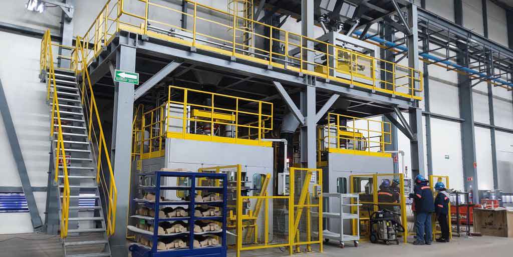
CAD technology enables the visualization and optimization of gating systems for steel castings in both 2D and 3D environments. We can model different gating layouts and analyze fluid flow patterns through simulation tools integrated into CAD software. The table below presents optimized gating parameters for large steel castings based on CAD-driven designs:
| Gating Component | Cross-Sectional Area (cm²) | Length (mm) | Flow Rate (kg/s) | Role in Steel Castings Pouring |
|---|---|---|---|---|
| Sprue | 50-200 | 300-800 | 100-500 | Channels metal from ladle to runner in steel castings |
| Runner | 30-150 | 500-2000 | 80-400 | Distributes metal to multiple ingates in steel castings |
| Ingate | 20-100 | 100-300 | 50-300 | Controls entry into mold cavity for steel castings |
In my experience, using CAD for gating system design in steel castings allows for rapid adjustment of parameters to achieve balanced filling. For example, we can apply the Bernoulli equation to model pressure drops: $$ P_1 + \frac{1}{2} \rho v_1^2 + \rho g h_1 = P_2 + \frac{1}{2} \rho v_2^2 + \rho g h_2 $$ where subscripts 1 and 2 refer to different points in the gating system for steel castings. CAD software automates these calculations, ensuring that the gating design minimizes turbulence and oxide formation in steel castings. Additionally, CAD supports the creation of detailed drawings with automatic dimensioning, reducing the time spent on manual drafting for steel castings.
Furthermore, CAD technology aids in optimizing the gating ratio for steel castings, which is crucial for controlling metal velocity and reducing defects. A typical gating ratio for steel castings might be 1:2:1 (sprue:runner:ingate), and CAD can simulate various ratios to find the optimal one. This iterative process enhances the quality of steel castings by promoting laminar flow and reducing slag inclusion. The integration of CAD with simulation tools also allows for thermal analysis, ensuring that the gating system maintains adequate temperature for proper solidification of steel castings. Overall, the application of CAD in gating system optimization for steel castings leads to improved casting yield and reduced scrap rates, contributing to the economic production of steel castings.
Application of CAD Technology in Chilling System Optimization for Steel Castings
Chills are essential in the casting of large steel castings to control solidification rates and prevent shrinkage defects in thick sections. CAD technology streamlines the design of chills by enabling precise placement and sizing based on thermal analysis. The design often relies on empirical rules, but CAD allows for more scientific approaches through simulation. The effectiveness of a chill in steel castings can be quantified by its chilling modulus (M_chill), similar to the casting modulus, calculated as: $$ M_{chill} = \frac{V_{chill}}{A_{chill}} $$ where V_chill is the volume of the chill and A_chill is its surface area in contact with the steel casting. CAD software can automatically compute these values and suggest optimal chill dimensions for steel castings.
In practice, I use CAD to model chills as part of the overall casting assembly for steel castings. The software helps determine the number and location of chills to achieve directional solidification, which is critical for steel castings. The table below summarizes common chill types and their applications in steel castings, derived from CAD-based optimizations:
| Chill Type | Material | Dimensions (mm) | Thermal Conductivity (W/m·K) | Use in Steel Castings |
|---|---|---|---|---|
| External Chill | Cast Iron | 50x50x100 | 40-50 | Placed on mold surface to cool thick sections of steel castings |
| Internal Chill | Steel | 20x20x50 | 15-25 | Embedded in the mold to accelerate cooling in core areas of steel castings |
| Graphite Chill | Graphite | 30x30x150 | 100-150 | Used for high heat extraction in critical zones of steel castings |
CAD technology facilitates the simulation of heat transfer between the steel casting and chills. Using Fourier’s law of heat conduction, we can analyze the temperature distribution: $$ q = -k \nabla T $$ where q is the heat flux, k is the thermal conductivity, and ∇T is the temperature gradient. CAD-integrated FEA tools solve these equations numerically, providing insights into how chills affect solidification patterns in steel castings. This allows for iterative design improvements, such as adjusting chill sizes or materials to optimize cooling rates for steel castings.
Moreover, CAD enables the creation of custom chills for complex geometries in steel castings. By importing 3D scans of the casting, we can design chills that conform perfectly to the mold surface, ensuring efficient heat extraction. This customization is particularly valuable for large steel castings with irregular shapes, where standard chills may not suffice. The automation in CAD reduces design time and improves accuracy, leading to better quality steel castings with minimized shrinkage and residual stresses. In summary, the application of CAD in chilling system optimization for steel castings enhances process control and product reliability, making it a vital tool in modern foundries specializing in steel castings.
Application of CAD Technology in Other Systems for Steel Castings
Beyond risers, gating, and chills, CAD technology plays a crucial role in optimizing other aspects of the casting process for steel castings. This includes the design of parting lines, core assemblies, venting systems, and process documentation. In large steel castings, these elements must be carefully planned to ensure mold integrity and casting quality. CAD software allows for integrated design, where all components are modeled in a single environment, facilitating coordination and error detection.
For parting line design in steel castings, CAD tools help determine the optimal mold separation plane based on geometry and draft angles. We can use algorithms to automatically generate parting lines that minimize undercuts and simplify mold manufacturing for steel castings. The software also calculates draft angles using formulas like: $$ \theta = \arctan\left(\frac{h}{d}\right) $$ where θ is the draft angle, h is the height, and d is the depth of the steel casting feature. This ensures easy ejection of the steel casting from the mold.
In core design for steel castings, CAD enables the creation of complex core assemblies that form internal cavities. The software can simulate core placement and verify clearances, reducing the risk of defects like core shift in steel castings. The table below highlights key considerations for core design in steel castings using CAD:
| Core Component | Material | Size (mm) | Support Mechanism | Impact on Steel Castings Quality |
|---|---|---|---|---|
| Main Core | Sand | 500-2000 | Chaplets | Forms internal features in steel castings |
| Vent Core | Ceramic | 50-200 | Integrated vents | Allows gas escape during pouring of steel castings |
| Insulating Core | Exothermic | 100-500 | Binding agents | Controls cooling rates in specific zones of steel castings |
CAD technology also streamlines the creation of process documentation for steel castings, such as casting process cards and inspection sheets. By automating drawing generation and annotation, CAD reduces manual effort and ensures consistency across designs for steel castings. Additionally, CAD systems can interface with enterprise resource planning (ERP) software to manage materials and scheduling for steel castings production. This holistic approach optimizes the entire workflow, from design to delivery, for steel castings.
Furthermore, CAD facilitates the integration of lean manufacturing principles in steel castings foundries. By simulating the entire casting process, we can identify bottlenecks and waste, leading to continuous improvement in steel castings production. For instance, CAD-based layout planning can optimize mold stacking and handling for large steel castings, reducing floor space and energy consumption. The ability to visualize and analyze every aspect of the process makes CAD an indispensable tool for achieving efficiency and sustainability in steel castings manufacturing.
Advanced CAD Techniques for Steel Castings Optimization
As CAD technology evolves, advanced techniques such as generative design, topology optimization, and digital twin integration are becoming increasingly relevant for steel castings. Generative design uses algorithms to explore multiple design alternatives based on constraints like weight, strength, and manufacturability for steel castings. This approach can lead to innovative riser and gating configurations that traditional methods might overlook. For example, generative design can optimize the shape of risers for steel castings to minimize material usage while maintaining feeding efficiency, using objective functions like: $$ \text{Minimize } V_{riser} \text{ subject to } M_{riser} > M_{casting} $$ where M_riser and M_casting are moduli for the riser and steel casting, respectively.
Topology optimization in CAD focuses on redistributing material within a component to enhance performance. For steel castings, this can be applied to the casting itself or to tooling like molds and cores. By using finite element analysis within CAD, we can identify regions of stress concentration in steel castings and suggest design modifications. The optimization process often involves solving equations like: $$ \text{Find } \rho(x) \text{ that minimizes } C(\rho) = \int_{\Omega} \sigma(\rho) : \epsilon(\rho) \, d\Omega $$ where ρ(x) is the material density distribution, C is compliance, σ is stress, and ε is strain for the steel casting. This results in lightweight yet strong steel castings, reducing costs and improving sustainability.
Digital twin technology, integrated with CAD, creates a virtual replica of the casting process for steel castings. This allows for real-time monitoring and predictive analytics, enabling proactive adjustments to improve quality. For instance, sensors on actual casting equipment can feed data into the CAD model, simulating how variations in pouring temperature or cooling rates affect the final steel casting. The digital twin can be described by differential equations modeling heat transfer and fluid flow: $$ \frac{\partial T}{\partial t} = \alpha \nabla^2 T $$ where T is temperature, t is time, and α is thermal diffusivity for the steel casting. By continuously updating the twin with real data, we can optimize process parameters dynamically for steel castings.
The table below compares traditional and CAD-driven advanced techniques for steel castings optimization:
| Technique | Traditional Approach | CAD-Driven Approach | Benefits for Steel Castings |
|---|---|---|---|
| Generative Design | Manual trial-and-error | Algorithmic exploration | Innovative designs, reduced weight in steel castings |
| Topology Optimization | Empirical ribbing | FEA-based material redistribution | Enhanced strength-to-weight ratio in steel castings |
| Digital Twin | Static process plans | Dynamic simulation with real data | Improved quality control and predictive maintenance for steel castings |
In my work, applying these advanced CAD techniques has led to significant improvements in the production of steel castings. For example, using generative design, we reduced riser volume by 15% for a large steel casting, lowering material costs without compromising integrity. Topology optimization helped redesign a structural steel casting to achieve 20% weight reduction while meeting load requirements. Digital twins enabled us to predict and prevent shrinkage defects in steel castings by adjusting chilling patterns in real-time. These advancements underscore the transformative potential of CAD in pushing the boundaries of steel castings manufacturing.
Conclusion
The integration of CAD technology in the casting process for large steel castings has revolutionized the industry, offering unparalleled advantages in design speed, accuracy, and optimization. From riser and gating systems to chilling and beyond, CAD enables engineers to automate calculations, simulate processes, and iterate designs rapidly. The use of formulas, such as modulus calculations and fluid dynamics equations, combined with tabular data, provides a scientific foundation for decision-making in steel castings production. Advanced techniques like generative design and digital twins further enhance capabilities, leading to innovative and efficient solutions for steel castings.
Throughout this article, I have emphasized the critical role of CAD in addressing the unique challenges of steel castings, such as shrinkage, thermal management, and geometric complexity. By leveraging CAD, foundries can improve yield, reduce waste, and accelerate time-to-market for steel castings. The continuous evolution of CAD software promises even greater integration with emerging technologies, fostering a future where steel castings are produced with higher precision and sustainability. As an engineer, I believe that embracing CAD is essential for staying competitive in the global market for steel castings, and I encourage ongoing exploration of its applications to unlock new potentials in casting process optimization for steel castings.
In summary, CAD technology is not just a tool but a catalyst for innovation in the casting of steel castings. Its ability to model, analyze, and optimize every aspect of the process makes it indispensable for modern foundries. As we move forward, the synergy between CAD and other digital technologies will continue to drive advancements, ensuring that steel castings meet the ever-increasing demands for quality, performance, and cost-efficiency. The journey of optimizing steel castings with CAD is an ongoing one, filled with opportunities for improvement and excellence in manufacturing.