
In the realm of heavy industrial equipment, the demand for large-scale components has driven the evolution of materials and manufacturing processes. Among these, spheroidal graphite cast iron, commonly known as ductile iron, stands out due to its excellent mechanical properties, cost-effectiveness, and relative ease of processing. As machinery grows in size and complexity, thick-section spheroidal graphite cast iron parts have become increasingly vital, offering advantages over steel castings, forgings, and other materials in applications requiring high strength, durability, and dimensional stability. This article details our comprehensive approach to developing a heavy-section spheroidal graphite cast iron tailstock for a high-pressure die-casting machine, focusing on casting process optimization, metallurgical control, and quality validation.
The tailstock is a critical component in the clamping mechanism of high-pressure die-casting machines, ensuring precise mold opening and closing, which directly impacts product accuracy and machine reliability. Our project involved producing a tailstock weighing 16.8 tons, with overall dimensions of 4,820 mm × 3,890 mm × 795 mm, featuring a complex “open” shape in plan view and an “L” profile in side view. The wall thickness ranged from a minimum of 100 mm to over 400 mm in the heaviest sections, classifying it as a thick-section casting. The material specification required QT500-7 grade spheroidal graphite cast iron, with stringent nondestructive testing standards: all machined surfaces needed 100% ultrasonic inspection per GB/T 34904—2017 Level 3, and general dimensional tolerances followed GB/T 6414—2017 CT 11. Such requirements posed significant challenges, including risks of graphite flotation, coarse microstructure, graphite degeneration, and shrinkage porosity, common in thick-section spheroidal graphite cast iron.
To address these challenges, we employed a systematic methodology integrating numerical simulation, advanced gating and feeding design, precise melting and treatment practices, and rigorous quality control. The goal was to achieve a sound casting with homogeneous microstructure and consistent mechanical properties. The following sections elaborate on each phase of the development process.
Casting Process Design and Numerical Simulation
The casting process was designed using a two-part mold (cope and drag) with physical patterns and core boxes. The outer mold was constructed using a combination of full-size expanded polystyrene (EPS) patterns and plywood plates for stability, with reinforcement ribs added during pattern making to prevent deformation during handling. For ease of molding, the tailstock was oriented with the “open” shape lying flat and protruding sections facing downward, placing the main body in the drag and making protruding blocks removable. The four shaft holes were produced using split core boxes.
The feeding system employed insulated risers of varying sizes tailored to local wall thicknesses to enhance feeding efficiency. Vent holes were strategically placed in the cope to allow gas escape. A bottom-gating, open-type system was chosen, utilizing ceramic tubes (known as “瓦筒” in the original text) for the gating system. The runner was positioned along the inner side of the casting, connected to the sprue via a cross-shaped transition runner, while multiple ingates, arranged evenly around the perimeter using bent pipes, introduced molten metal dispersedly. A slag trap was incorporated to improve metal cleanliness during filling.
Given the prolonged solidification times in thick sections, which can lead to defects, chill plates were strategically placed in heavy-wall regions to accelerate local cooling, balance thermal gradients, and refine microstructure. The layout and specifications of chills were marked on plywood plates for precise placement during molding. The mold and core sands were phenolic-modified furan resin self-setting sand, chosen for high strength and stiffness to maximize the graphitization expansion self-feeding effect inherent in spheroidal graphite cast iron, thereby suppressing shrinkage porosity.
Numerical simulation played a pivotal role in validating the process design. Using commercial casting simulation software, we modeled the solidification process, including 3D geometry import, mesh generation, setting initial and boundary conditions (e.g., pouring temperature, heat transfer coefficients), and running simulations to predict solidification sequences and defect formation. The simulation focused on typical thick sections in X-Z and Y-Z planes, tracking the fraction solid and temperature distribution from mold filling to complete solidification.
The solidification progression, as shown in simulation snapshots, indicated that regions with chills solidified rapidly, directing the solidification front from lower thick sections upward toward the risers. No isolated liquid pools were observed. In the Y-Z plane, the left side (without riser intersection) solidified earlier than the right thicker region, but the final solidification points were consistently concentrated in the risers, confirming their effectiveness as feeding sources. The overall solidification sequence aligned with process intentions, promoting directional solidification toward the risers.
Predicted shrinkage porosity, displayed as scattered, small-scale regions in simulation results, indicated low risk of major defects. This is attributed to the wide eutectic solidification range of spheroidal graphite cast iron; with adequate mold rigidity, effective inoculation, appropriate pouring temperature, and controlled operations, the self-feeding effect from graphite expansion can compensate for shrinkage, minimizing porosity. Thus, the simulation affirmed the feasibility of the process scheme.
Melting, Nodulization, and Inoculation Practices
The chemical composition of the spheroidal graphite cast iron was carefully controlled to meet QT500-7 specifications while ensuring good castability and microstructure in thick sections. The target composition range is summarized in Table 1.
| Element | Range |
|---|---|
| Carbon (C) | 3.3–3.7 |
| Silicon (Si) | 1.9–2.3 |
| Manganese (Mn) | 0.3–0.6 |
| Phosphorus (P) | ≤0.04 |
| Sulfur (S) | ≤0.02 |
| Magnesium (Mg) | 0.04–0.06 |
| Rare Earth (RE) | 0.01–0.03 |
Raw materials included high-purity pig iron (Q10 grade), clean steel scrap, and returns from the same material. Steel scrap was free of contaminants like sealed containers, combustibles, explosives, or toxic substances. Returns, such as risers and scrap castings, were limited to a controlled proportion to maintain composition stability. All charge materials were cleaned to minimize rust and oil.
Melting was conducted in a 30-ton medium-frequency coreless induction furnace. The charging sequence followed: steel scrap first, then pig iron, and finally returns. After melting, slag was removed, and composition adjustments were made. The molten iron was superheated to above 1,500°C, held for 5–10 minutes for homogenization and impurity removal, then allowed to cool naturally to 1,410–1,450°C before tapping. During tapping, a barium-silicon inoculant was added in-stream to initiate preconditioning.
Nodulization was performed using the wire-feeding method, which offers precise control over magnesium addition and reduces fading effects. The treatment temperature ranged from 1,350 to 1,390°C. The wire contained magnesium and rare earth elements to promote graphite spheroidization. Simultaneously, inoculation was carried out to enhance graphite nucleation. After treatment, slag was thoroughly skimmed, and the melt surface was covered with insulating compounds to prevent reoxidation and sulfur reversion.
Multistage inoculation was employed to improve inoculation efficiency, particularly late-stage inoculation, which is crucial for thick-section spheroidal graphite cast iron to avoid undercooling and graphite degeneration. The mold cavity was cleaned and preheated to eliminate moisture and contaminants. A basin-type pouring cup was used, containing silicon-iron inoculant blocks for additional post-inoculation during pouring.
Pouring was done with a single 30-ton ladle at a temperature of 1,300–1,340°C. The entire process from nodulization completion to pouring end was tightly controlled within 25 minutes to minimize magnesium fade and inoculation decay. After pouring, risers were covered with exothermic materials to maintain thermal gradient and feeding efficiency.
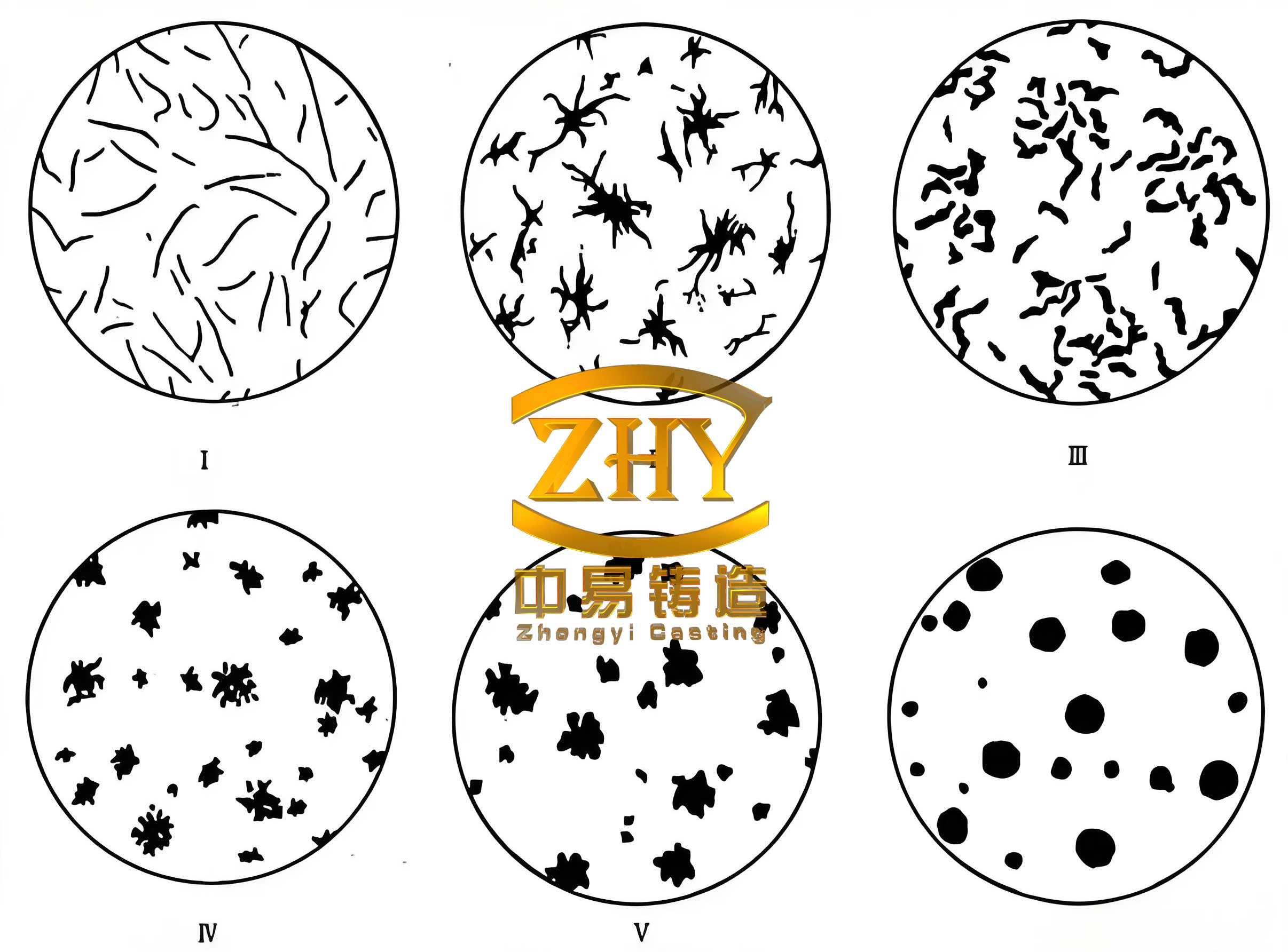
The quality of spheroidal graphite cast iron is governed by three key metrics: nodularity (percentage of spherical graphite), graphite nodule size, and nodule count. Optimal microstructure features small, numerous, uniformly distributed, and well-rounded graphite nodules. The inoculation practice aimed to achieve this, as described by the kinetics of graphite growth. The growth rate of graphite nodules can be approximated by:
$$ \frac{dr}{dt} = k \cdot (C – C_{eq}) $$
where \( r \) is the nodule radius, \( t \) is time, \( k \) is a kinetic constant, \( C \) is the actual carbon concentration in the melt, and \( C_{eq} \) is the equilibrium carbon concentration at the solidification interface. Effective inoculation increases nucleation sites, reducing \( C – C_{eq} \) and promoting finer nodules.
Production Verification and Results
The casting was produced according to the optimized process. After shakeout and cleaning, the as-cast tailstock was visually inspected and subjected to nondestructive testing. Ultrasonic testing per GB/T 34904—2017 Level 3 revealed no significant internal defects, confirming the casting’s soundness and compliance with stringent quality requirements.
Mechanical properties were evaluated using specimens extracted from attached test blocks (as per casting standards). The results, averaged over three samples, are presented in Table 2, showing full conformity with QT500-7 specifications.
| Property | Required (QT500-7) | Measured Average |
|---|---|---|
| Yield Strength (MPa) | ≥290 | 347 |
| Tensile Strength (MPa) | ≥420 | 485 |
| Elongation (%) | >5 | 10 |
| Hardness (HB) | 170–230 | 190 |
Metallographic analysis was conducted on samples from the attached test blocks. The microstructure exhibited a nodularity of 90%, with graphite nodules rated as size 6 according to standard charts. The matrix consisted of ferrite and pearlite, with pearlite content around 5%. This microstructure is typical of QT500-7 spheroidal graphite cast iron, offering a good balance of strength and ductility. The graphite morphology can be quantified by nodule count per unit area, which for our casting was in the range of 120–150 nodules/mm², indicating effective inoculation.
The success of this thick-section spheroidal graphite cast iron tailstock demonstrates the importance of integrated process control. Factors such as mold stiffness, cooling rate management via chills, and multistage inoculation contributed to minimizing defects and achieving consistent properties. The numerical simulation provided valuable insights for optimizing riser and chill placement, reducing trial-and-error iterations.
Discussion on Thick-Section Spheroidal Graphite Cast Iron Characteristics
Producing heavy-section spheroidal graphite cast iron involves addressing several metallurgical challenges. The slow cooling rates in thick sections can lead to graphite flotation, where graphite nodules float to the upper regions due to density differences, causing inhomogeneity. This is mitigated by controlling carbon equivalent (CE) and using chills to accelerate solidification. The carbon equivalent is calculated as:
$$ CE = C + \frac{Si + P}{3} $$
For our casting, CE was maintained around 4.2–4.5, within the typical range for thick-section spheroidal graphite cast iron to avoid excessive graphite formation while ensuring good fluidity.
Another issue is carbide formation, especially in regions with high cooling rates or insufficient inoculation. However, in thick sections, the risk is lower due to slower cooling, but inoculation remains critical to prevent chill carbides. Our multistage inoculation approach ensured sufficient nucleation sites throughout solidification.
The self-feeding effect from graphite expansion is a key advantage of spheroidal graphite cast iron. During eutectic solidification, the volume expansion from graphite formation can compensate for shrinkage, reducing porosity. This effect is maximized with high mold stiffness, as provided by resin sand molds. The pressure generated by expansion can be estimated as:
$$ P_{exp} = \frac{E \cdot \Delta V}{V} $$
where \( P_{exp} \) is the expansion pressure, \( E \) is the modulus of elasticity of the mold, \( \Delta V \) is the volume change due to graphite expansion, and \( V \) is the initial volume. Adequate mold rigidity ensures this pressure is effectively transmitted to liquid regions, enhancing feeding.
Graphite nodule characteristics directly influence mechanical properties. The relationship between nodule size and tensile strength can be expressed by the Hall-Petch type equation for spheroidal graphite cast iron:
$$ \sigma_y = \sigma_0 + k \cdot d^{-1/2} $$
where \( \sigma_y \) is yield strength, \( \sigma_0 \) and \( k \) are constants, and \( d \) is the average graphite nodule diameter. Finer nodules (smaller \( d \)) lead to higher strength, underscoring the need for effective inoculation.
Industrial Implications and Future Directions
The development of this tailstock highlights the viability of spheroidal graphite cast iron for large, complex components in heavy machinery. As die-casting machines and other equipment continue to scale up, the demand for such castings will grow. Our process framework—combining simulation, advanced treatment methods, and rigorous quality control—provides a replicable model for other thick-section spheroidal graphite cast iron applications, such as wind turbine hubs, press frames, or marine components.
Future work could focus on further optimizing the chemistry for enhanced properties, such as using alloying elements like copper or nickel to increase pearlite content for higher strength grades. Additionally, real-time monitoring during melting and treatment, such as thermal analysis or spectroscopy, could improve process consistency. Research on alternative inoculation materials or methods, like late-stream inoculation with specialized alloys, may also benefit thick-section spheroidal graphite cast iron production.
Conclusion
Through a holistic approach integrating numerical simulation, tailored casting design, controlled melting and nodulization via wire-feeding, and multistage inoculation, we successfully produced a heavy-section spheroidal graphite cast iron tailstock meeting stringent quality standards. The casting exhibited excellent mechanical properties, sound internal integrity, and a desirable microstructure with high nodularity and fine graphite nodules. This achievement underscores the capability of spheroidal graphite cast iron to replace more expensive materials in large-scale applications, offering a cost-effective solution without compromising performance. The insights gained from this project contribute to the broader knowledge base for manufacturing thick-section spheroidal graphite cast iron components, paving the way for further innovations in the field.