
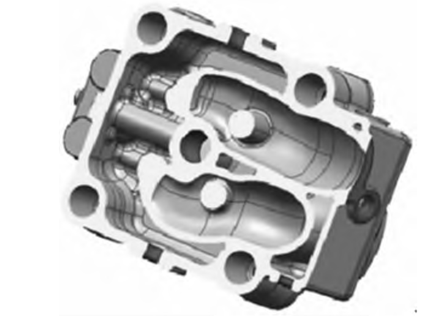
The upper front bearing seat is a critical component in automotive front suspension systems and aircraft landing gear, providing structural support for wheel rotation bearings. Its function requires maintaining stable connections between wheels and suspension systems while withstanding complex dynamic loads during operation. Manufactured from HT-250 gray cast iron, this material offers excellent castability, good mechanical properties, vibration resistance, and cost-effectiveness for medium-load applications. However, the seat’s structural complexity—with dimensions of 1085 mm × 810 mm × 380 mm, wall thickness variations from 20 mm to 150 mm, and net weight of 566 kg—poses significant challenges in defect prevention during the casting process.
Process Analysis and Initial Design
The asymmetric wall thickness distribution creates thermal gradients that promote shrinkage porosity and cavities. Critical areas include thin-walled oil injection holes susceptible to core damage and thick-section transitions acting as natural hot spots. Key casting process parameters were established based on manual resin sand molding requirements:
| Parameter | Value | Standard Reference |
|---|---|---|
| Dimensional Tolerance | CT13 | Casting Process Design Manual |
| Machining Allowance | Grade G | |
| Shrinkage Rate | 0.9% | |
| Riser Cutting Allowance | 3 mm | |
| Cooling Time | 60 min | Technical Specification |
Two pouring position alternatives were evaluated (Figure 2 reference omitted per requirements). Scheme 1 oriented the bearing base upward, facilitating mold assembly but increasing hot spot risks in thick lower sections. Scheme 2 positioned the base downward, improving surface quality but requiring risky mold flipping. Based on solidification simulations, Scheme 2 was selected due to its superior thermal profile control.
Gating System Engineering
A bottom-gated semi-closed system was designed to ensure smooth filling with reduced turbulence. The gating ratio followed established standards: $$ \Sigma A_{\text{spru}} : \Sigma A_{\text{runner}} : \Sigma A_{\text{ingate}} = 1 : 1.25 : 0.83 $$ Critical dimensions were calculated through fundamental hydraulic principles:
Pouring time was determined by: $$ t = S_1 \sqrt[3]{\delta G_L} $$ where \( t \) = filling time (s), \( S_1 \) = empirical coefficient (1.8), \( \delta \) = average wall thickness (42 mm), and \( G_L \) = molten metal weight (700 kg). This yielded \( t \) = 43 s.
Minimum sprue height preventing misruns was calculated as: $$ H_M = L \tan \alpha $$ with \( L \) = 300 mm (longest flow path) and \( \alpha \) = 30° (pressure angle), giving \( H_M \) = 173 mm. Actual height was set at 360 mm.
Choke area was derived from Bernoulli’s equation: $$ A_g = \frac{G}{\rho t \mu \sqrt{2g H_p}} $$ where \( \rho \) = 7,200 kg/m³, \( \mu \) = 0.5 (flow coefficient), \( g \) = 9.81 m/s², and \( H_p \) = 360 mm. This produced \( A_g \) = 1,700 mm².
| Component | Cross-section (mm²) | Geometry | Quantity |
|---|---|---|---|
| Sprue | 2,040 | Conical (Ø50→Ø62) | 1 |
| Runner | 2,550 | Trapezoidal | 2 |
| Ingate | 1,700 | Trapezoidal | 4 |
Numerical Simulation and Defect Analysis
ProCAST simulations at 1,350°C pouring temperature revealed critical issues in the initial casting process:
- Filling time: 43 s with acceptable velocity fields below 2.5 m/s
- Temperature differentials: 250°C between thin upper walls and thick junctions
- Shrinkage defects: 0.48% total volume concentrated in four regions
Defect distribution analysis showed:
- Upper protrusions: 32% of total porosity due to inadequate feeding
- Sidewall junctions: 41% from thermal isolation
- Gating system: 27% (acceptable)
Optimization Methodology
First-stage modifications addressed feeding deficiencies through riser design. Riser neck diameter was calculated as: $$ d_R = (1.48 \sim 2.5) M_C $$ where \( M_C \) = casting modulus (\( V_C / A_C \)). For protrusions with \( M_C \) = 30 mm, \( d_R \) = 60 mm. Four cylindrical risers (Ø60 × 180 mm) were added.
Chills were placed at high-risk junctions using: $$ \delta_{\text{chill}} = (0.25 \sim 0.5) T $$ where \( T \) = 75 mm (hotspot diameter), giving \( \delta_{\text{chill}} \) = 30 mm. Two chills (100 × 100 × 30 mm) were positioned.
Post-optimization simulations showed residual porosity at 0.31%, primarily in small upper protrusions. Second-stage enhancements included:
- Riser redesign: Two large risers (Ø90 × 270 mm) replacing three smaller units
- Additional risers: Three miniature risers (Ø41 × 124 mm) for protrusions
- Chill expansion: Four chills with improved contact surfaces
Final Casting Process Validation
The optimized casting process achieved near-zero defects in functional areas:
| Defect Metric | Initial | Stage 1 | Stage 2 |
|---|---|---|---|
| Total Porosity (%) | 0.48 | 0.31 | 0.05 |
| Critical Zone Defects | 73% volume | 39% volume | <1% volume |
| Process Yield | 85% | 88% | 90.5% |
Key features of the validated casting process include:
- Pouring orientation: Base-down configuration with mold rotation
- Gating system: Bottom-fed semi-closed design with optimized ratios
- Feeding: Five strategically placed risers with volume-adjusted dimensions
- Cooling: Four chills at critical junctions accelerating solidification
- Process parameters: 1,350°C pouring, 43 s fill time, resin sand molds
Conclusion
This systematic optimization demonstrates that bottom-gated systems combined with computational modeling effectively address defects in complex castings. The implementation of modulus-based riser design and thermally balanced chilling reduced shrinkage porosity by 90% while maintaining process efficiency. The methodology provides a framework for similar medium-section gray iron components requiring high structural integrity. Future work will explore automated gating optimization algorithms to further enhance the casting process robustness.