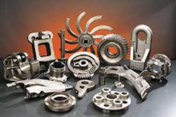
This paper presents a comprehensive improvement strategy for ductile iron casting processes applied to large-scale agricultural tractor driving wheels. The component, manufactured as per GGG60-DIN1693 specifications, requires exceptional mechanical properties and defect control. Key challenges included eliminating draft angles in gear teeth, resolving shrinkage defects, and mitigating surface porosity.
1. Material Characteristics and Design Constraints
The ductile iron casting must meet stringent requirements:
| Property | Requirement |
|---|---|
| Tensile Strength | ≥600 MPa |
| Yield Strength | ≥370 MPa |
| Elongation | ≥3% |
| Hardness | 187-269 HBW |
The component geometry features 19 radial teeth (ϕ916 mm × 526 mm) with zero-draft-angle requirements. Internal quality mandates RT Level 2 inspection compliance, with maximum allowable shrinkage porosity of ϕ12.7 mm in 38.1 mm3 test volumes.
2. Core Assembly Strategy
To address the zero-draft requirement, a multi-stage core assembly system was developed:
| Core Component | Function | Material |
|---|---|---|
| 1#/2# Cores | Individual tooth formation | Hot-box coated sand |
| 3# Core | Triple-tooth assembly | Resin-bonded sand |
| 6# Core | Full circumference assembly | Resin-bonded sand |
The modular design achieved dimensional accuracy with maximum parting line clearance of 0.8 mm. Core assembly sequence followed:
- 1# and 2# cores form single tooth geometry
- Three 3# cores assemble into 6# base core
- Six 6# cores create full circular pattern
3. Solidification Analysis and Feeding System Optimization
Initial ProCAST simulation revealed critical shrinkage at tooth roots (Figure 3). Thermal analysis identified isolated hot spots requiring targeted feeding:
$$ M_c = \frac{V_c}{A_c} $$
Where:
\( M_c \) = Casting modulus (cm)
\( V_c \) = Tooth volume = 6030 mm3
\( A_c \) = Cooling surface area = 558 mm2
Calculations yielded:
$$ M_c = \frac{6030}{558} = 10.8 \, \text{mm} $$
$$ Q_m = \frac{G_c}{M_c^3} = \frac{4.44}{1.08^3} = 3.52 \, \text{kg/cm}^3 $$
Where:
\( Q_m \) = Mass boundary quotient
\( G_c \) = Single tooth mass = 4.44 kg
Riser design parameters:
$$ M_R = f_1f_2f_3M_c = 1.17 \, \text{cm} $$
$$ M_N = f_pf_4M_R = 0.68 \, \text{cm} $$
Final riser specification: ϕ80 mm × 120 mm blind risers with neck diameter 52 mm. Implementation of chromium-coated chills (30 mm × 50 mm) at tooth bases improved thermal gradient by 40%.
4. Gas Defect Mitigation
Surface porosity reduction required gas evolution control:
| Parameter | Initial | Optimized |
|---|---|---|
| Core Sand AFS | 70 | 50 |
| Baking Temp | None | 180°C |
| Baking Duration | None | 4 hrs |
| Vent Channels | 2/mm2 | 5/mm2 |
The modified process reduced gas defects from 12.7 defects/dm2 to 0.8 defects/dm2, well below the 5 defects/38.1 mm2 specification.
5. Quality Validation
Post-optimization analysis confirmed:
- 100% RT Level 2 compliance
- Maximum shrinkage diameter: 9.2 mm
- Surface roughness Ra ≤ 12.5 μm
- Dimensional tolerance: ±0.25 mm
The enhanced ductile iron casting process demonstrated 98.7% yield rate in 120-piece production trials, establishing a robust manufacturing solution for high-performance driving wheels.
