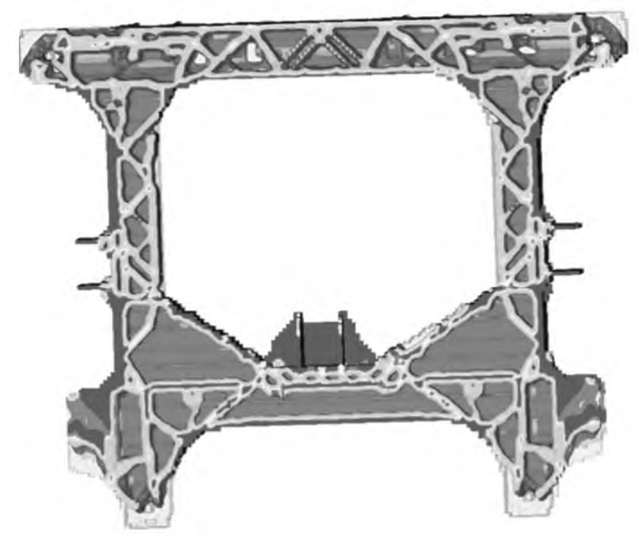
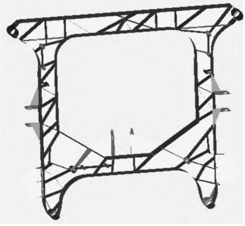
As a core component of the automotive chassis structure, the subframe plays a role in load-bearing and vibration isolation. Its optimized design aims to improve the structural strength, stiffness, safety and other performance of the car, and achieve weight reduction. This article will explore the specific technical route for optimizing the design of the subframe structure, in order to provide valuable reference for the design of the subframe structure.
Structural optimization design refers to the process of optimizing the shape, size, material, etc. of engineering structures based on specific objectives and constraints using computer technology and numerical simulation methods. Its purpose is to achieve maximum structural lightweighting and improve the relevant performance indicators of the structure while meeting design requirements. Structural optimization has derived different optimization techniques such as topology optimization, size optimization, morphology optimization, and shape optimization based on the requirements of different design stages.
The optimization object of ZHY Casting is a welded subframe, and after considering the optimization objectives of the new product comprehensively, the optimization direction is determined as an integrated die casting subframe. The integrated die casting subframe has the advantages of high strength, light weight, few welds, low manufacturing cost, and high stability in terms of structure and technology.
1. Optimize target extraction
The design of the subframe includes performance indicators such as strength, stiffness, NVH, modal, and collision. Perform finite element analysis on the benchmark components (welded subframe) separately, and use the analysis results of each performance index as optimization indicators.
1.1 Strength analysis of welded subframe
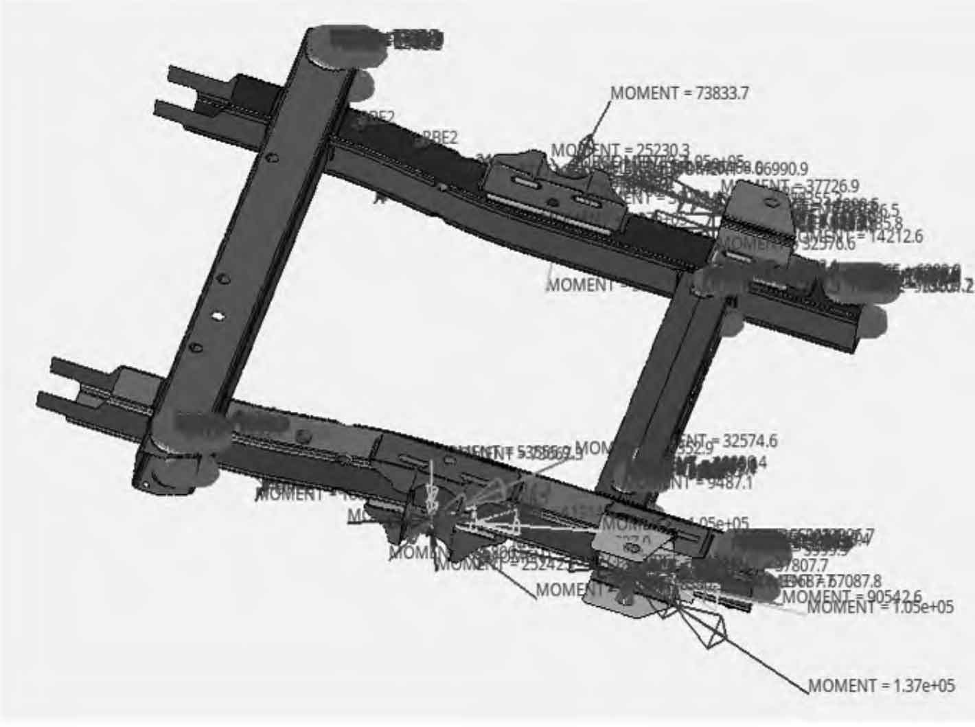
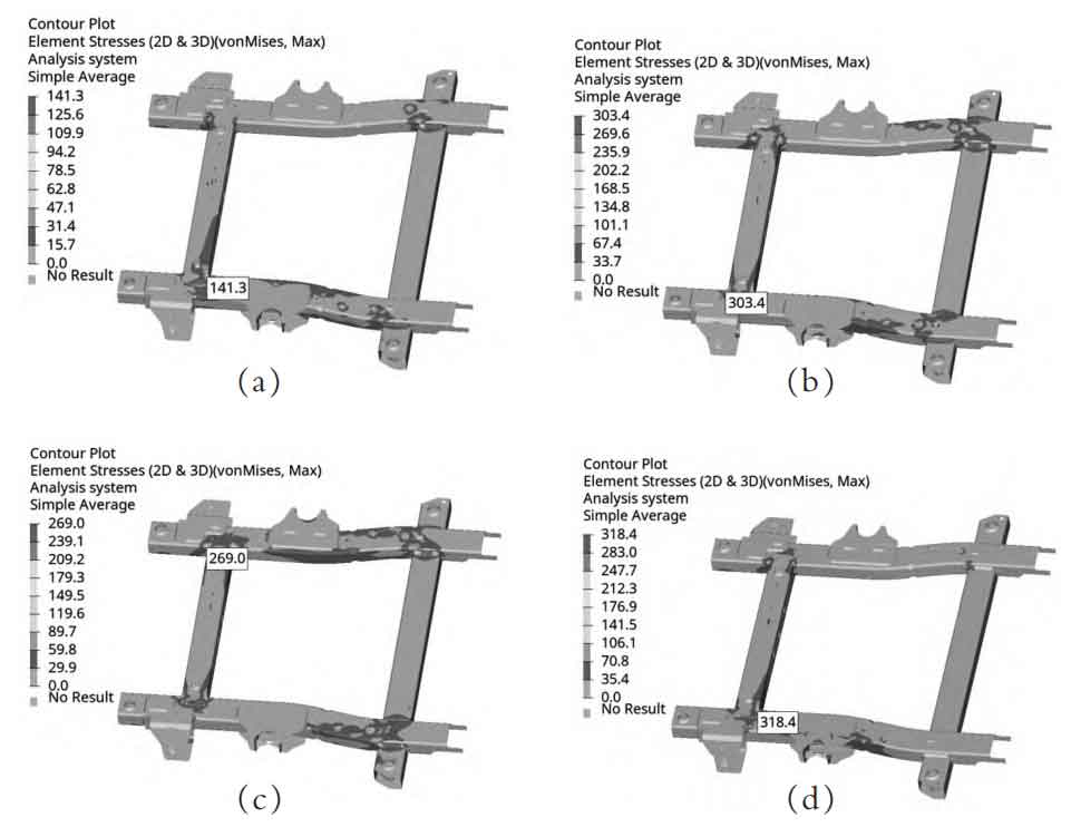
To obtain the input of the strength condition of the subframe, a multi rigid body model was built in the multi-body dynamics analysis software and kinematic analysis was performed to extract the load information of each attachment point of the subframe. The load information is shown in Figure 1. Input the obtained load into the finite element model of the subframe for strength analysis using inertial release. Considering the actual needs of structural optimization in the later stage, four envelope working condition groups, namely working condition 1, working condition 5, working condition 6, and working condition 9, were extracted as strength indicators.
The stress cloud maps for four envelope working conditions are shown in Figure 2. For the convenience of comparison, the stress extreme values of the four strength working conditions are recorded in Table 1.
| Working conditions | Maximum stress (MPa) |
| 1 | 141.3 |
| 2 | 303.4 |
| 3 | 269.0 |
| 4 | 318.4 |
1.2 Stiffness and Modality of Jointed Subframe
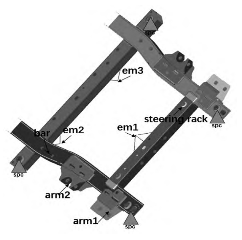
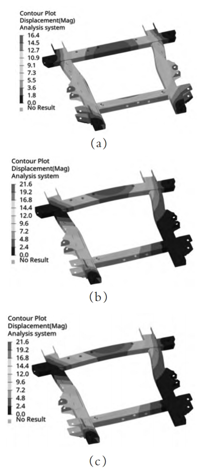
Stiffness condition calculation: Apply three loads to the lower swing arm, motor, steering gear, and stabilizer bar attachment points to constrain the vehicle suspension installation point. The attachment points and constraint information are shown in Figure 3. Calculate and record the stiffness values as shown in Table 2. Constrain 6 degrees of freedom at the vehicle body connection point, calculate the constrained mode as shown in Figure 4, and record the results of the first 3 modes as shown in Table 3. The three-dimensional stiffness calculation results of each attachment point are shown in Table 2.
| Working conditions | F | Stiffness (N/mm) |
| arm1 | X | 58824 |
| arm1 | Y | 62500 |
| arm1 | Z | 610.9 |
| arm2 | X | 18519 |
| arm2 | Y | 23810 |
| arm2 | Z | 5525 |
| bar | X | 125000 |
| bar | Y | 28571 |
| bar | Z | 17241 |
| steering rack | X | 90909 |
| steering rack | Y | 76923 |
| steering rack | Z | 13699 |
| em1 | X | 25641 |
| em1 | Y | 4167 |
| em1 | Z | 3410 |
| em2 | X | 10870 |
| em2 | Y | 2597 |
| em2 | Z | 15625 |
| em3 | X | 7692 |
| em3 | Y | 2933 |
| em3 | Z | 8929 |
| Order | Modal (Hz) |
| 1 | 274.8 |
| 2 | 366.3 |
| 3 | 371.4 |
1.3 Dynamic stiffness of welded subframe
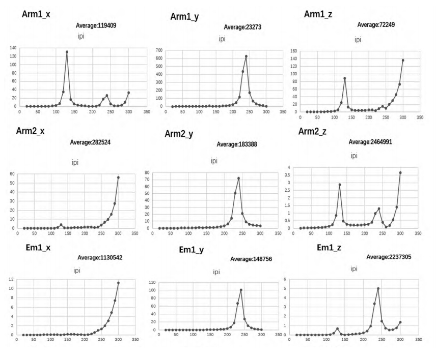
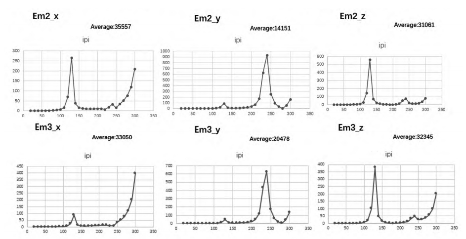
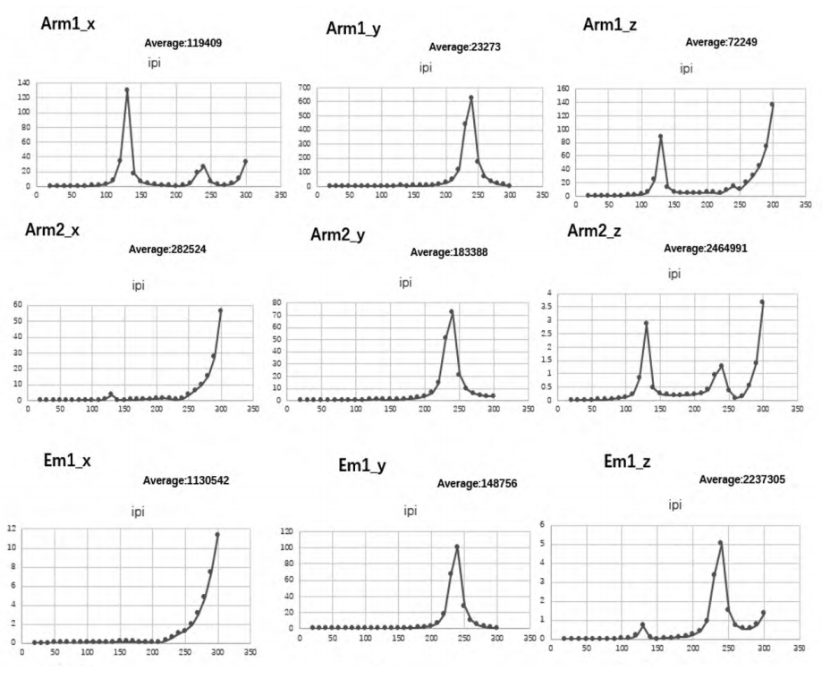
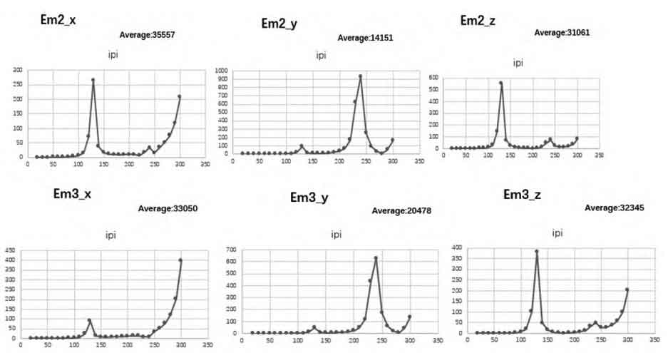
According to the actual connection method of each installation point, select the lower swing arm and motor installation points for dynamic stiffness calculation and performance target extraction. The calculation results are shown in Figure 5. Summarize the calculation results in Table 4.
| Working conditions | F | Stiffness (N/mm) |
| arm1 | X | 119409 |
| arm1 | Y | 23273 |
| arm1 | Z | 72249 |
| arm2 | X | 282524 |
| arm2 | Y | 183388 |
| arm2 | Z | 2464991 |
| em1 | X | 1130542 |
| em1 | Y | 148756 |
| em1 | Z | 2237305 |
| em2 | X | 35557 |
| em2 | Y | 14151 |
| em2 | Z | 31061 |
| em3 | X | 33050 |
| em3 | Y | 20478 |
| em3 | Z | 32345 |
2. Optimization of subframe structure
The structural optimization of the subframe is divided into two stages. In the first stage, topology optimization is carried out to re plan the load transfer path of the structure and improve the performance of the integrated die casting subframe; In the second stage, parameter optimization is carried out to optimize the thickness layout of the materials and achieve lightweight of the integrated die casting subframe.
2.1 Subframe topology optimization
2.1.1 Basic principles of topology optimization
Topology optimization is a technique of optimizing design by changing the shape and layout of a structure. Topology optimization methods mainly include homogenization method, variable density method, asymptotic structural optimization method, level set method, etc. The basic principle of the variable density method is to divide the design domain into many small units, each of which can have different pseudo material densities. Then, through iterative calculation, under the constraint conditions, the material is transferred from the unwanted area to the desired area to achieve optimization goals such as stiffness, mass, and mode.
2.1.2 Mathematical model construction
The optimization of the subframe involves stiffness, strength, dynamic stiffness, and modal indicators, which can be divided into two categories according to different optimization strategies. Among them, stiffness, strength, and modal can be normalized to the minimum flexibility objective, while dynamic stiffness aims to minimize mass. Establish constraint sets for each objective, and use MMO technology to superimpose the two optimization results to obtain the optimal integrated die casting subframe structure. According to the above description, the optimized mathematical model will be constructed as follows:
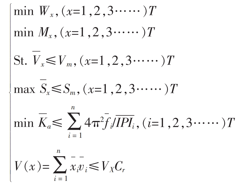
Among two independent normalized objectives, Wx represents the target flexibility value, x represents each volume optimization variable, Mx represents the total target mass, and x represents each mass optimization variable. The flexibility normalization constraint function is represented by a volume fraction Vx less than the set target value Vm and a maximum stress Sx less than the set target value Sm. The quality normalization objective function uses weighted IPI for the second type of response constraint.
MMO optimization uses parallel technology to composite different objectives or similar types of optimizations, and after optimization, it can obtain structures that meet the performance requirements of multiple types. MMO calls two different target FEM files through the main control file. The main control file used for this optimization is as follows:
SCREEN OUT

RESPRINT ALL

TITLE=MultipLE MODELS Optimization

ASSIGN, MMO, Model1, master.fm

ASSIGN, MMO, Mode2, static.fm

ASSIGN, MMO, Mode3, dynamic.fm

BEGIN BULK

ENDDATA
In the main control file, static.fm calls the result of stiffness optimization, while dynamic.fm calls the result of dynamic stiffness optimization, calling 4 threads for optimization.
2.1.3 Optimization Results and Interpretation
After multiple rounds of process and parameter adjustment, the ideal subframe optimization results are shown in Figure 6. From the optimization results, it can be seen that the layout of the integrated die casting subframe is carried out in a unidirectional pulling and reinforcing manner, which is in line with the design concept of integrated die casting. The optimization results are clear and the load transfer path is reasonable. Interpret and reshape the optimization results as shown in Figure 7.
2.2 Optimization of subframe parameters
After topology optimization, a reasonable subframe structure was obtained. In order to obtain a lightweight subframe structure with reasonable thickness distribution, the size parameters of the new structure were optimized.
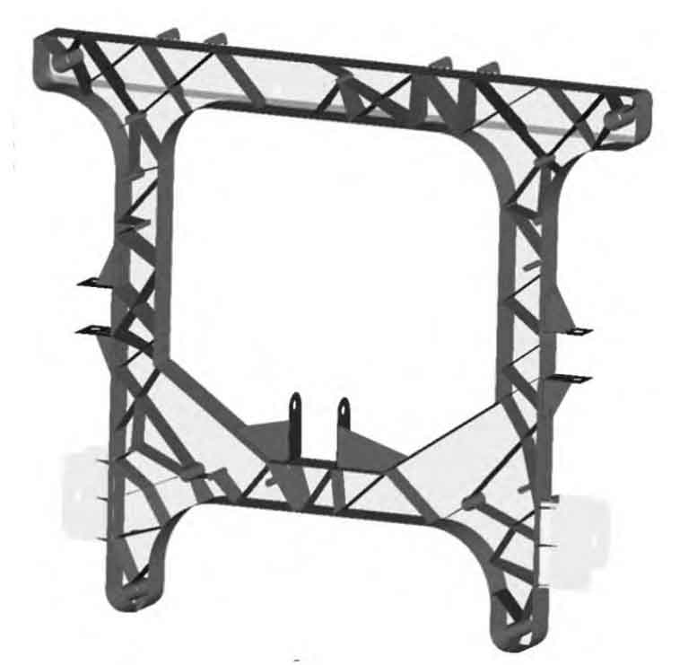
To obtain the ultimate results of dimensional changes, the outer wheel profile and all reinforcement ribs of the integrated die casting subframe are completely discretized, and the percentage of optimized upper and lower limits is set according to process requirements. Discretization resulted in a total of 32 design variables, and the setting of optimization objectives and constraints remained consistent with topology optimization. Obtain the final optimization result as shown in Figure 8, and update the optimization result to the model to complete the final design of the new structure.
3. New structure validation
Conduct a comprehensive analysis of the integrated die casting subframe using the same modeling standards and calculation conditions, and compare the analysis results with the welded subframe to ensure the rationality of the new structural design.
3.1 Strength analysis and comparison of integrated die casting subframe
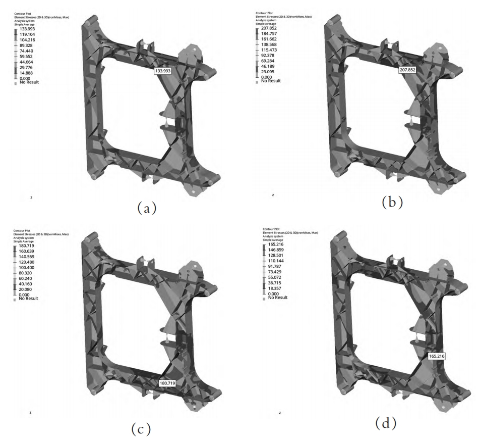
The four envelope strength working conditions of the new structure are shown in Figure 9. The calculation results are compared with the welded subframe as shown in Table 5. From the calculation results, it can be seen that the maximum stress of the integrated die casting subframe (operating condition 4) has been reduced by 153.2 MPa, and the strength has increased by 48.1%.
| Working conditions | Maximum stress of welded subframe (MPa) | Maximum stress of integrated die-casting subframe (MPa) |
| 1 | 141.3 | 134.0 |
| 2 | 303.4 | 207.9 |
| 3 | 269.0 | 180.7 |
| 4 | 318.4 | 165.2 |
3.2 Rigidity and Modal Analysis and Comparison of Integrated Die Casting Subframe
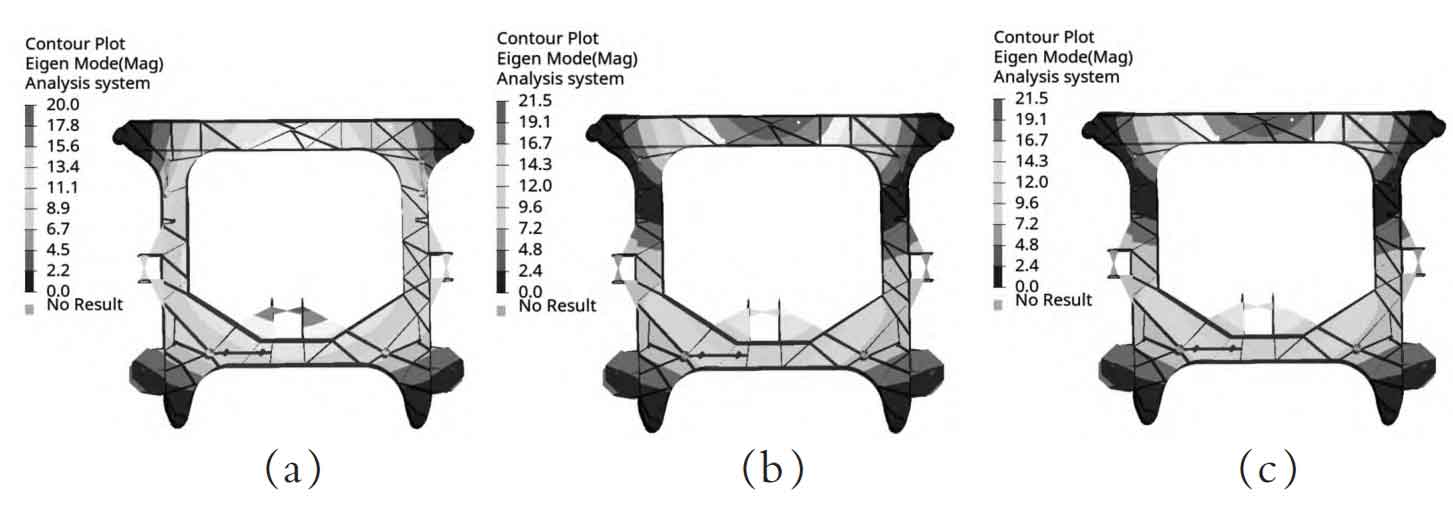
The modal analysis results of the integrated die casting subframe are shown in Figure 10, and the modal analysis results are summarized in Table 6. From the comparison of modal analysis results, it can be seen that the first-order modal of the integrated die casting subframe has increased by 16.5%. The stiffness analysis results and comparison of each attachment point are shown in Table 7. From the analysis results, it can be seen that the stiffness of each attachment point has also been improved to varying degrees.
| Working conditions | Splice welded subframe mode (Hz) | Integrated die-casting subframe mode (Hz) |
| 1 | 274.8 | 320.1 |
| 2 | 366.3 | 367.7 |
| 3 | 374.1 | 389.8 |
| Working conditions | F | Splice welded subframe stiffness (N/mm) | Integrated die cast subframe stiffness (N/mm) |
| arm1 | X | 58824 | 66666.66 |
| arm1 | Y | 62500 | 71428.57 |
| arm1 | Z | 610.9 | 2857.40 |
| arm2 | X | 18519 | 22727.27 |
| arm2 | Y | 23810 | 32258.06 |
| arm2 | Z | 5525 | 5780.34 |
| bar | X | 125000 | 125000.00 |
| bar | Y | 28571 | 100000.00 |
| bar | Z | 17241 | 29411.76 |
| steering rack | X | 90909 | 142857.40 |
| steering rack | Y | 76923 | 66666.66 |
| steering rack | Z | 13699 | 16949.15 |
| em1 | X | 25641 | 41666.66 |
| em1 | Y | 4167 | 4878.04 |
| em1 | Z | 3410 | 3472.22 |
| em2 | X | 10870 | 16949.15 |
| em2 | Y | 2597 | 4587.15 |
| em2 | Z | 15625 | 28571.42 |
| em3 | X | 7692 | 10204.08 |
| em3 | Y | 2933 | 4672.89 |
| em3 | Z | 8929 | 11363.63 |
3.3 Dynamic stiffness analysis and comparison of new structures
The results of the dynamic stiffness analysis of the new structure are shown in Figure 11. The calculation results are summarized in Table 8 and compared with the basic model. Through comparison, it can be seen that the dynamic stiffness of the new structure has been improved to varying degrees, with the attachment point of swing arm 2 being increased by 3.2 times.
| Working conditions | F | Splice welded subframe stiffness (N/mm) | Integrated die cast subframe stiffness (N/mm) |
| arm1 | X | 119409 | 147226 |
| arm1 | Y | 23273 | 23592 |
| arm1 | Z | 72249 | 133455 |
| arm2 | X | 282524 | 120642 |
| arm2 | Y | 183388 | 184599 |
| arm2 | Z | 2464991 | 2464991 |
| em1 | X | 1130542 | 1859280 |
| em1 | Y | 148756 | 149572 |
| em1 | Z | 2237305 | 2241147 |
| em2 | X | 35557 | 44174 |
| em2 | Y | 14151 | 17304 |
| em2 | Z | 31061 | 32862 |
| em3 | X | 33050 | 43660 |
| em3 | Y | 20478 | 22372 |
| em3 | Z | 32345 | 33047 |
3.4 Weight and cost comparison
Further optimize the connection process of the integrated die casting subframe after structural optimization, and record the cost and weight results of the basic structure and new structure in Table 9 and 10. Through a comprehensive analysis and comparison of the welded subframe and the integrated die casting subframe, it can be seen that the integrated die casting subframe has comprehensive weight and cost advantages. The weight of the integrated die casting subframe is 2.03kg lower than that of the welded subframe, a decrease of 16.3%; The cost decreased by 41.62 yuan, a decrease of 8.6%.
| Part number | Part Name | Quantity | Unit price (yuan) | Total price (yuan) |
| F33015 | Front subframe assembly | 1 | 456.53 | 456.53 |
| M10X1.25×50-4.5 | Aluminum sleeve | 4 | 6 | 24 |
| M6x17.5 | Flat head round body knurled open end rivet nut | 9 | 0.08 | 0.72 |
| M8x19 | Flat head round body knurled open end rivet nut | 3 | 0.14 | 0.42 |
| / | Total cost | / | / | 481.67 |
| Part number | Part Name | Quantity | Unit price (yuan) | Total price (yuan) |
| F33015 Front subframe assembly 1 436.8 436.8 | Front subframe assembly | 1 | 436.8 | 436.8 |
| ST10-1.25D Steel wire screw sleeve 4 0.3 1.2 | Steel wire screw sleeve | 4 | 0.3 | 1.2 |
| M6x17.5 Flat head round body knurled open end rivet nut 2 0.08 0.16 | Flat head round body knurled open end rivet nut | 2 | 0.08 | 0.16 |
| ST6-1.5D Steel wire screw sleeve 7 0.19 1.33 | Steel wire screw sleeve | 7 | 0.19 | 1.33 |
| M8x19 Flat head round body knurled open end rivet nut 1 0.14 0.14 | Flat head round body knurled open end rivet nut | 1 | 0.14 | 0.14 |
| ST8-1.5D Steel wire screw sleeve 2 0.21 0.42 | Steel wire screw sleeve | 2 | 0.21 | 0.42 |
| / | Total cost | / | / | 440.05 |
4. Conclusion
(1) Integrated die casting subframe performance improvement. In the optimization design of the subframe, parametric optimization methods have been introduced. By optimizing the thickness of the reinforcing ribs and outer contour of the integrated die casting subframe, the stiffness, dynamic stiffness, and modal of the subframe have been successfully improved. The improvement of the dynamic stiffness of the integrated die casting subframe can effectively reduce the distortion and deformation of the vehicle body, improve driving stability and ride comfort. From the optimization in this article, it can be seen that while lightweight, there is also the possibility of performance improvement. Therefore, a more reasonable structural design is an important way to improve the cost-effectiveness of the integrated die casting subframe.
(2) The integrated die casting subframe structure is lightweight. Through topology optimization, the lightweight design of the integrated die casting subframe has been successfully achieved. Compared with traditional design, the newly designed integrated die casting subframe reduces weight by 16.3% while meeting performance requirements such as stiffness, strength, dynamic stiffness, and modal. We have comprehensively applied the three major lightweight methods of structure, technology, and materials, forming a complete set of lightweight technology routes for reference in the same industry.
(3) The subframe technology is lightweight and cost-effective. Replacing the welded subframe with an integrated die casting subframe greatly reduces the processing steps, while the non welded structural form enhances the strength of the structure. By further optimizing the connection method, the integrated die casting subframe has achieved further cost reduction.
The optimization design of the subframe structure is one of the important topics in the field of modern automotive engineering. The comprehensive application of topology optimization, material optimization, and structural parameter optimization methods can effectively improve the structural performance of integrated die casting subframes, and meet the requirements of the automotive manufacturing industry for lightweight, safety, and economy. In the future, with the development of technology and the advancement of computer technology, the optimized design of integrated die casting subframes will play a more important role in automotive engineering, contributing to the realization of intelligent, green, and sustainable automotive manufacturing.

