

1. Introduction
Investment casting, also known as lost-wax casting, is a precision casting process that has been widely used in the manufacturing industry for producing complex and high-quality metal components. In the context of the oil drilling industry, ductile iron protective parts play a crucial role in ensuring the safety and reliability of drilling operations. This article focuses on the optimization of the investment casting process for ductile iron drilling machine protective parts, aiming to enhance the quality of the castings and reduce the occurrence of defects.
The ductile iron protective parts are essential components of the oil drilling machine, providing protection against various mechanical and environmental stresses. However, the traditional investment casting process for these parts often suffers from problems such as shrinkage porosity and inclusions, which can significantly affect the performance and durability of the castings. Therefore, it is necessary to conduct in-depth research and optimization to improve the casting quality.
2. Casting Structure and Requirements
2.1 Structure of the Ductile Iron Protective Part
The ductile iron protective part is a hollow cylindrical component with a relatively simple structure. It has an average wall thickness of 20 mm and features three asymmetric slots at one end, eight through-holes between the two end faces, and a toothed groove on the outer cylindrical surface. The outer contour dimensions of the part are 148.49 mm × 148.49 mm × 71.1 mm.
2.2 Material and Mechanical Properties
The material used for the casting is QT600 ductile iron, with the following chemical composition (mass fraction, %): 3.0 – 3.5 C, 2.4 – 2.8 Si, 0.3 – 0.5 Mn, 0.03 – 0.035 S, P < 0.1, 0.045 – 0.050 Mg. The tensile strength of the casting is required to be ≥ 600 MPa, and the hardness is in the range of HB 190 – 270. The solidification temperature range of the alloy is 1129 – 1194 °C, and the density is 7300 kg/m³.
2.3 Quality Requirements
The casting is required to have no surface and internal casting defects to ensure its reliable performance in the oil drilling environment. Any defects such as shrinkage porosity, shrinkage cavities, inclusions, or surface roughness can lead to premature failure of the protective part and pose a risk to the safety of the drilling operation.
3. Original Investment Casting Process
3.1 Pouring System Design
The original pouring system adopted a combination of a sprue, runner, ingate, and riser. To improve production efficiency, a one-mold-four-piece combination was used. The sprue was designed to ensure a smooth filling process and good feeding of the casting to achieve sequential solidification and prevent shrinkage defects.
3.2 Filling Speed Calculation
The filling speed was calculated using the Calking formula:
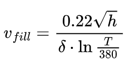
where Vfill is the minimum allowable rising speed of the metal liquid surface in the casting cavity (cm/s), h is the casting height (cm), δ is the casting wall thickness (cm), and T is the alloy pouring temperature (°C). Based on the calculated value, a filling speed of 0.458 m/s was selected considering various factors.
3.3 Main Process Parameters
The liquidus and solidus temperatures of the ductile iron QT600 were 1194 °C and 1129 °C, respectively. The shell consisted of 6 layers with a thickness of approximately 6 mm, made of refractory quartz sand and bonded with silica sol. The pouring process was carried out in air using a top gating system. The shell preheating temperature was 900 °C, and the casting was poured in the negative X direction under gravity with a pouring temperature of 1300 °C and a filling speed of 0.458 m/s. The casting was cooled naturally.
4. Numerical Simulation of the Original Process
4.1 3D Model Establishment and Mesh Generation
The 3D model of the ductile iron protective part was created using Pro/E software, and the pouring system model was also established. The model was then imported into ProCAST software for mesh generation. The total number of nodes for the casting was 67,010.
4.2 Simulation Parameter Settings
In the ProCAST software, material properties and boundary conditions were set. The heat transfer coefficients were determined based on experience and typical values: the heat transfer coefficient between the shell and the casting was 1000 W/(m²·K), between the casting and air was 1000 W/(m²·K), and between the shell and air was 50 W/(m²·K). The gravity direction of the casting was set as negative X with a value of 9.8 m/s².
4.3 Results and Analysis
4.3.1 Filling Process
The filling process of the original scheme showed that the molten metal was injected smoothly, with minimal impact on the cavity wall. The sprue was filled in 0.7 s, and the two workpieces in the first group were filled in 2.5 s, while the two workpieces in the second group were more than half filled in 3.4 s and completely filled in 7.2 s.
4.3.2 Solidification Process
During the solidification process of the casting, the solidification occurred in the order of from outside to inside and from bottom to top. At 944 s, the casting started to solidify from the outside, and then the solidification front advanced from the farthest part from the ingate to the ingate. At 1774 s, the main body of the casting was about to complete solidification, and the entire casting system was completely solidified at 2704 s.
4.3.3 Shrinkage Defects
The simulation results of the shrinkage porosity distribution of the original process showed that shrinkage porosity was prone to occur in the sprue, ingate, and their connection parts. The shrinkage porosity rate was 13.2603%, and the presence of many shrinkage pores in the casting body affected the casting quality, leading to product rejection. This was consistent with the main cause of product rejection in actual production. The unreasonable setting of the process scheme and parameters resulted in the inability to compensate for the volume shrinkage of the casting during solidification, thus causing shrinkage defects.
5. Process Optimization
5.1 Improvement of the Pouring System
Based on the analysis of the original process, two optimization schemes were proposed. Scheme A added an ingate on the rectangular side of the original pouring system, and Scheme B added an ingate in the pipe part. Numerical simulations were carried out for both schemes to compare their effects on reducing shrinkage defects.
5.2 Comparison of Different Schemes
The shrinkage porosity distribution of different schemes was analyzed. The shrinkage porosity rate of Scheme A was 6.9025%, and that of Scheme B was 1.3675%. Scheme B had the smallest shrinkage porosity rate and no shrinkage porosity defects in the casting body. Therefore, Scheme B was considered more reasonable compared to Scheme A and the original scheme.
6. Optimization of Casting Process Parameters
6.1 Selection of Parameter Levels
Three casting process parameters that affect the quality of investment castings were studied: pouring temperature, filling speed, and shell preheating temperature. Based on production experience and relevant research, the following levels were selected for each parameter:
| Parameter | Levels |
|---|---|
| Pouring Temperature (°C) | 1250, 1280, 1300 |
| Filling Speed (m/s) | 0.450, 0.455, 0.460 |
| Shell Preheating Temperature (°C) | 800, 900, 1000 |
6.2 Orthogonal Experimental Design
An orthogonal experiment was designed to study the influence of these parameters on the shrinkage porosity rate of the casting. The factors and levels of the orthogonal experiment are shown in the following table:
| Level | Factor A (Pouring Temperature/°C) | Factor B (Filling Speed/(m·s⁻¹)) | Factor C (Shell Preheating Temperature/°C) |
|---|---|---|---|
| 1 | 1250 | 0.450 | 800 |
| 2 | 1280 | 0.455 | 900 |
| 3 | 1300 | 0.460 | 1000 |
6.3 Experimental Results and Analysis
Nine groups of experiments were carried out according to the orthogonal experiment design, and the filling time and shrinkage porosity rate of each group were obtained. The results are shown in the following table:
| Test No. | Factor A | Factor B | Factor C | Filling Time (s) | Shrinkage Porosity Rate (%) |
|---|---|---|---|---|---|
| L1 | 1 | 1 | 1 | 4.881 | 1.451 |
| L2 | 1 | 2 | 2 | 3.925 | 1.433 |
| L3 | 1 | 3 | 3 | 3.869 | 1.442 |
| L4 | 2 | 1 | 2 | 3.961 | 1.551 |
| L5 | 2 | 2 | 3 | 3.918 | 1.452 |
| L6 | 2 | 3 | 1 | 3.869 | 1.402 |
| L7 | 3 | 1 | 3 | 3.820 | 1.589 |
| L8 | 3 | 2 | 2 | 3.771 | 1.370 |
| L9 | 3 | 3 | 1 | 3.858 | 1.321 |
The range analysis of the orthogonal experiment results showed that the combination of A3B3C1 was the optimal process parameter group, with a pouring temperature of 1300 °C, a filling speed of 0.460 m/s, and a shell preheating temperature of 800 °C. The shrinkage porosity rate of the casting under this parameter combination was 1.321%, and the filling time was 3.858 s.
7. Verification of the Optimized Process
7.1 Numerical Simulation of the Optimized Process
The optimized process parameters were used for numerical simulation of the casting process. The simulation results showed that the shrinkage porosity rate of the casting was significantly reduced, and the distribution of shrinkage porosity was more favorable. The shrinkage porosity rate of the optimized casting was only 1.321%, which was much lower than that of the original process.
7.2 Actual Casting Production Verification
Actual casting production was carried out using the optimized process. The castings obtained had a lower rejection rate and better quality compared to those produced by the original process. The surface quality and internal structure of the castings were inspected, and no significant defects were found, confirming the effectiveness of the process optimization.
8. Conclusion
8.1 Summary of the Optimization Process
In this study, the investment casting process for ductile iron drilling machine protective parts was optimized through a series of steps. The original process was analyzed using numerical simulation, and the causes of shrinkage porosity and other defects were identified. Based on this, the pouring system was improved, and an orthogonal experiment was conducted to optimize the casting process parameters. The optimized process parameters were verified through numerical simulation and actual casting production.
8.2 Significance of the Optimization Results
The optimization of the investment casting process for ductile iron protective parts has significant practical significance. It not only improves the quality of the castings, reduces the rejection rate, and saves production costs but also provides a theoretical basis and practical reference for the production of other similar castings. The use of ProCAST software for numerical simulation and the orthogonal experiment method for parameter optimization proved to be effective in improving the casting process.