
Lost foam casting (LFC) has become a critical technology for producing complex thin-walled castings, especially semi-enclosed structures widely used in mechanical equipment. This paper systematically explores process innovations to address common defects such as sand collapse and dimensional distortion in large-to-medium semi-enclosed castings through practical case studies.
1. Process Design and Implementation
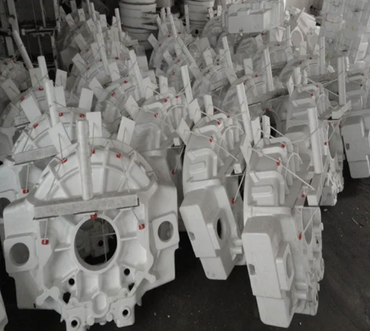
The production process for semi-enclosed castings includes four key stages: pattern fabrication, coating application, sand filling/vibration, and molten metal pouring. Critical parameters are summarized below:
| Process Stage | Coating Thickness (mm) | Drying Temp (°C) | Drying Time (h) |
|---|---|---|---|
| First Coat | 0.8–1.2 | 35–45 | 20 |
| Second Coat | 1.2–1.5 | 40–50 | 24 |
| Third Coat | 1.5–2.0 | 45–50 | 26 |
The vacuum pressure gradient during pouring significantly impacts casting quality. The required negative pressure can be calculated using:
$$ P_v = \frac{F_r \cdot \rho_m \cdot g \cdot h_c}{A_e} $$
Where \( P_v \) = vacuum pressure (kPa), \( F_r \) = safety factor (1.2–1.5), \( \rho_m \) = metal density (kg/m³), \( h_c \) = casting height (m), and \( A_e \) = effective evacuation area (m²).
2. Defect Analysis and Countermeasures
Typical defects in semi-enclosed castings include internal cavity deformation (30–40 mm dimensional deviation) and sand collapse. Root causes were identified through DOE:
| Element | C | Si | Mn | Cr | Ni | Mo | Cu | P | S |
|---|---|---|---|---|---|---|---|---|---|
| Content (%) | ≤0.25 | ≤0.35 | ≤0.60 | ≤0.15 | ≤0.40 | ≤0.05 | ≤0.40 | ≤0.035 | ≤0.035 |
Key improvement measures include:
- Tilted Molding: 45° inclination pattern placement improves sand flowability and compaction uniformity
- External Vacuum System: Dual vacuum channels maintain pressure balance between internal/external cavities
3. Vacuum System Optimization
The redesigned vacuum system features:
- 150 mm diameter negative pressure pipes
- 2 mm perforations with 15×10 mm spacing
- Double-layer steel mesh filtration
The vacuum equilibrium equation demonstrates system effectiveness:
$$ \Delta P = P_{ext} – P_{int} = \frac{Q}{A_v} \left( \frac{\mu}{2\rho} \right)^{1/2} $$
Where \( Q \) = gas flow rate (m³/s), \( A_v \) = vacuum pipe cross-section (m²), \( \mu \) = dynamic viscosity (Pa·s), and \( \rho \) = gas density (kg/m³).
| Parameter | Original | Improved | Change |
|---|---|---|---|
| Vacuum Pressure (kPa) | 0.25–0.35 | 0.40–0.50 | +60% |
| Sand Compaction Density (g/cm³) | 1.55–1.65 | 1.72–1.80 | +9.7% |
| Yield Rate (%) | 40 | 90 | +125% |
4. Implementation Results
Field tests demonstrated significant improvements:
- Sand collapse rate reduced from 35% to 4%
- Dimensional accuracy improved by 82%
- Post-casting repair costs decreased by 70%
The optimized lost foam casting process proves particularly effective for complex semi-enclosed structures, achieving stable production of castings with wall thickness ≤6 mm and internal cavities ≥800 mm in length.