It can be seen from the analysis that there is no liquid metal feeding at the center of the wheel due to the early solidification around the wheel, resulting in shrinkage porosity and shrinkage defects. In order to solve the problem that molten metal cannot be fed in time, a riser is added at the center of the wheel; Due to the complex structure of the casting, it is difficult to avoid the generation of hot spots, so add chill in the middle of the casting to match with the riser and improve the feeding efficiency of molten metal.
1. Design of riser and external chill
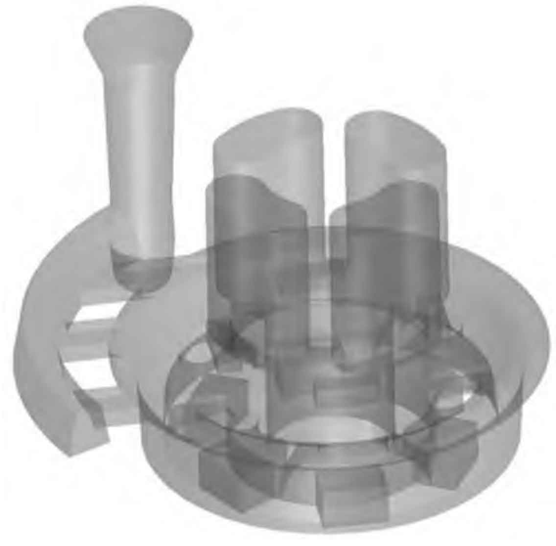
In order to ensure the smooth feeding of molten metal during solidification, it is necessary to ensure that the solidification time of riser is greater than or equal to the solidification time of casting. The modulus method is used to calculate the riser, and the modulus of the casting, m casting =1.173, and the modulus of the riser, m riser =1.55 are obtained respectively, which satisfies the relationship that M riser ≥ F1 · m casting, where F1 is the balance coefficient of the riser, and F1 ≥ 1.2. Check the feeding liquid volume of riser and bring it into the formula (V casting +v riser)· ε ≤ V riser· η, Where ε Is the shrinkage of condensed solids, η Is the feeding efficiency of riser. Through calculation, the riser can provide enough feeding liquid, and the castings meet the requirements of sequential solidification. The casting material is zg50mn2, which is a steel casting. High carbon steel is selected as the material of external chill. The optimized gating system is shown in Figure 1.
2. Simulation analysis after process optimization
Through the above scheme, the original gating system is optimized, and the optimized gating system is obtained, which is analyzed by numerical simulation. With the original setting parameters unchanged, set the heat exchange coefficient between chill and sand box to 500 w/ (mm2 · K), and the heat exchange coefficient between chill and casting to 2000 w/ (mm2 · K). Get the temperature field image as shown in Figure 2.
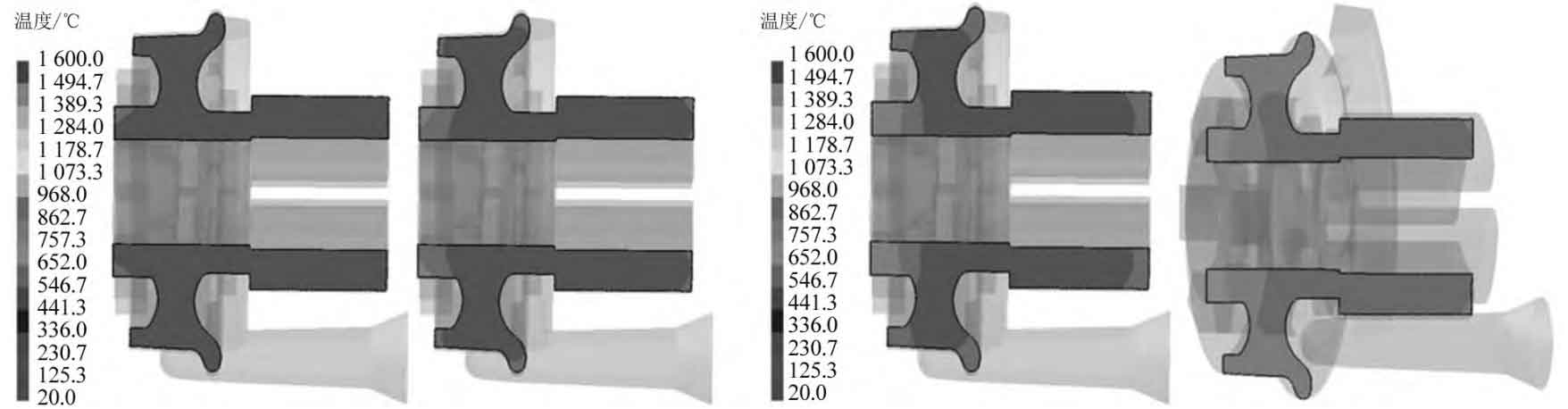
(c) Solidification fraction 70% (d) Solidification fraction 90%
It can be seen from Figure 2 that the wheels are basically solidified from top to bottom under the action of external chill and riser. It can be seen from figure 2A that the overall temperature of the wheel is higher, and the temperature at the edge decreases, which is lower than the liquidus temperature; It can be seen from figure 2B that the surrounding of the wheel begins to solidify; It can be seen from figure 2C that under the action of chill, the casting gradually solidifies from bottom to top, from outside to inside; It can be seen from figure 2D that the outer ring of the wheel is basically solidified, and the wheel hub is fed by the riser liquid metal and the effect of cold iron. There is no hot spot and isolated liquid phase area. Figure 3 shows the temperature diagram of different areas of wheel casting. According to the temperature distribution curve, the temperature at point C, that is, the riser position, is the highest, indicating that the riser is finally solidified.
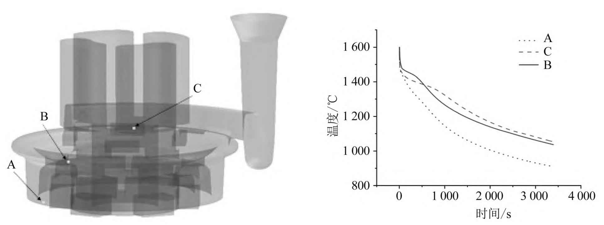
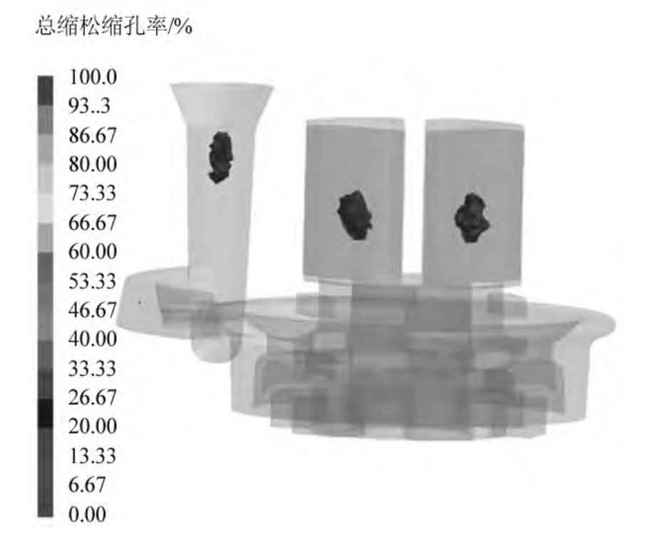
Figure 4 shows the distribution of shrinkage porosity and shrinkage cavity after optimization. It can be seen from Figure 4 that there are no casting defects such as shrinkage porosity and shrinkage cavity in the wheel casting, which shows that the defects of the casting in the casting process can be effectively improved by adding risers and external chill. The external chill can effectively avoid the generation of hot spots and improve the compactness of the casting.
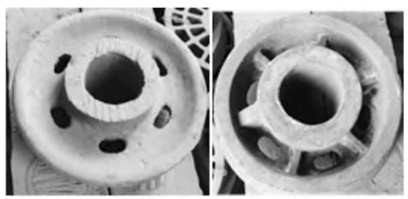
From the above simulation results, it can be seen that through the optimization of the wheel gating system of the mining flat car, the defects of the wheel casting are successfully eliminated. The improved casting process is verified in production. The microstructure and mechanical properties of the casting meet the requirements after practical production verification. The qualified products are shown in Figure 5.