
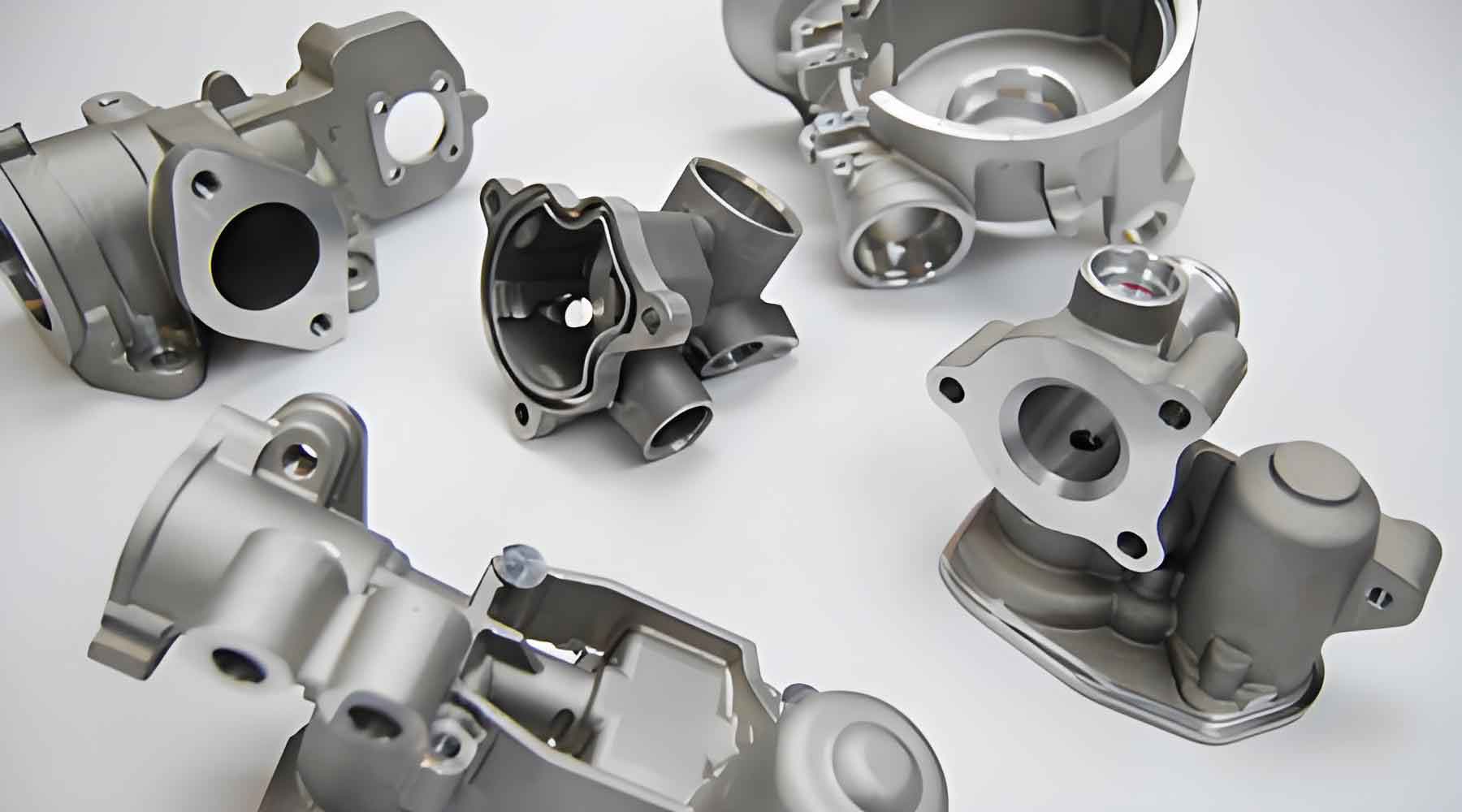
Precision investment casting enables the production of near-net-shape components with complex geometries, such as closed impellers for turbomachinery. This study focuses on optimizing the casting process for a duplex stainless steel (A890 3A) closed impeller using numerical simulation and experimental validation. Key parameters, including gating design, feeding systems, and pouring methods, were systematically analyzed to eliminate shrinkage defects and enhance yield rates.
Material Characteristics and Process Fundamentals
The duplex stainless steel exhibits a biphasic microstructure consisting of approximately 50% ferrite (α) and 50% austenite (γ). The thermal properties critical for casting simulation are summarized in Table 1.
| Parameter | Value | Unit |
|---|---|---|
| Liquidus Temperature | 1,450 | °C |
| Solidus Temperature | 1,380 | °C |
| Specific Heat Capacity | 500 | J/kg·K |
| Thermal Conductivity | 25 | W/m·K |
| Latent Heat of Fusion | 270 | kJ/kg |
The solidification behavior follows the Fourier heat transfer equation:
$$ \frac{\partial T}{\partial t} = \alpha \nabla^2 T $$
where α represents thermal diffusivity (α = k/ρcp), and T is temperature distribution.
Numerical Simulation Framework
ProCAST simulations employed the following boundary conditions:
- Mesh density: 706,712 volume elements
- Interfacial heat transfer coefficient: 500 W/m²·K
- Pouring temperature: 1,620°C
- Shell preheat temperature: 650°C
The critical shrinkage porosity criterion was defined as:
$$ P_{crit} = \frac{\Delta V}{V_0} \geq 2.3\% $$
where ΔV represents volumetric contraction during solidification.
Gating System Optimization
Initial trials revealed shrinkage defects at hub and shroud regions due to inadequate feeding. The optimization strategy involved:
| Parameter | Initial Design | Optimized Design |
|---|---|---|
| Number of Gates | 3 | 6 |
| Riser Diameter | 150 mm | 170 mm |
| Pouring Orientation | Central | Peripheral |
| Feeding Distance | Lf = 4.5√M | Lf = 6.2√M |
The feeding distance relationship follows:
$$ L_f = k \sqrt{M} $$
where M denotes modulus (volume/surface area ratio) and k is the feeding efficiency coefficient.
Thermal Management Strategy
Modified pouring orientation reduced thermal accumulation at the hub region. The temperature gradient (G) and solidification rate (R) relationship was optimized to prevent shrinkage:
$$ G \cdot R \geq \frac{\Delta T}{t_f} $$
where ΔT is freezing range and tf is local solidification time.
Industrial Validation
Production trials demonstrated:
- Defect rate reduction from 12.4% to 2.1%
- Yield improvement from 78% to 95%
- Dimensional accuracy within CT9 per ISO 8062
This case study confirms that precision investment casting combined with computational modeling provides an effective solution for manufacturing complex hydraulic components. The methodology establishes a technical framework for optimizing feeding systems and thermal management in thin-thickness varying castings.