
In the field of industrial manufacturing, particularly for components used in harsh chemical environments, the demand for high-integrity castings is paramount. As an engineer specializing in foundry processes, I have extensively worked on improving the quality of complex castings through precision lost wax casting. This investment casting method, known for its ability to produce intricate shapes with excellent surface finish and dimensional accuracy, is often the preferred choice for critical parts like pump bodies. However, the process is not without challenges, especially when dealing with alloys like CF8 stainless steel and geometries that promote defect formation. In this article, I will detail my experience in optimizing the precision lost wax casting process for a CF8 stainless steel pump body, focusing on the use of numerical simulation to eliminate shrinkage defects. The keyword ‘precision lost wax casting’ will be central to our discussion, as it underscores the meticulous control required in every step, from pattern making to final solidification.
The pump body in question is a crucial component in chemical pump systems, where it must withstand acidic media, high pressures, and cyclic loading. Failure due to internal defects like shrinkage porosity or cavities can lead to catastrophic leaks and operational downtime. Therefore, achieving sound internal structure and high surface quality is non-negotiable. The CF8 alloy, akin to ASTM A351 CF8, offers good corrosion resistance and mechanical properties, but its casting characteristics, such as solidification range and thermal conductivity, necessitate careful process design. The essence of precision lost wax casting lies in its multi-step approach: creating a wax pattern, building a ceramic shell, dewaxing, and pouring molten metal. Each step must be optimized to control the thermal history and fluid flow, ensuring the final casting meets stringent standards.
To begin, let’s analyze the structural aspects of the pump body casting. The component has a complex geometry with varying wall thicknesses, which inherently creates thermal gradients during solidification. Key features include inlet and outlet flanges, internal flow channels, and pump feet, all contributing to disparate cooling rates. The table below summarizes the chemical composition of CF8 stainless steel, which directly influences its solidification behavior and susceptibility to defects.
| Element | Composition (wt.%) |
|---|---|
| C | 0.06 |
| Mn | 1.1 |
| Si | 0.7 |
| Cr | 17.5 |
| Ni | 8.2 |
| Mo | 0.2 |
| S | 0.009 |
| Fe | Balance |
This composition results in a液相线温度 (liquidus temperature) of approximately 1,451°C and a固相线温度 (solidus temperature) around 1,370°C, giving a freezing range of about 81°C. In precision lost wax casting, such a range can promote mushy zone formation, increasing the risk of microporosity if not properly fed. The casting’s dimensions are 304 mm × 246 mm × 165 mm, with a weight of 24.75 kg. The wall thickness varies from 11 mm to 30 mm, with the flanges being the thickest sections. These thick regions act as thermal hotspots, requiring adequate feeding to compensate for volumetric shrinkage during solidification. The fundamental challenge in precision lost wax casting for this part is to design a gating and feeding system that ensures directional solidification toward the feeders, avoiding isolated liquid pools.
My initial approach involved designing a top-gating system based on empirical rules, aiming for sequential solidification from the bottom upwards. The gating system comprised multiple ingates targeting the hot spots: two ingates for the inlet flange, one for the outlet flange with a feed aid, and two for the pump feet. The dimensions were calculated using modulus methods, where the modulus ratio between feeder and casting section should ideally exceed 1.2 for effective feeding. However, due to geometric constraints, some ratios were lower. The table below outlines the initial gating system dimensions.
| Component | Dimensions (mm) | Purpose | Modulus Ratio |
|---|---|---|---|
| Ingate 1 (two units) | 80 × 60 × 40 | Feed inlet flange | 1.15 |
| Ingate 2 | 90 × 55 × 60 | Feed outlet flange with feed aid | 1.18 |
| Ingate 3 (two units) | 30 × 40 × 20 | Feed pump feet | 0.9 |
| Runner 1 | 330 × 70 × 70 | Distribute metal | – |
| Runner 2 | 250 × 40 × 45 | Connect ingates | – |
| Sprue | 60 × 60 × 80 | Vertical channel | – |
| Open Riser (two units) | Ø83/Ø120/Ø160 | Feed system and provide head | – |
The total height of the assembly was 435 mm, with risers connected by ties to equalize temperature. Despite this design, trial productions revealed shrinkage porosity at the junction between the pump feet and the flow channel. This indicated a flaw in the solidification sequence, likely due to premature isolation of that region. In precision lost wax casting, where the use of chills is limited by the ceramic shell, controlling solidification through gating design is critical. To diagnose the issue, I turned to numerical simulation using ProCAST software, a powerful tool for visualizing filling and solidification dynamics.
Numerical simulation in precision lost wax casting allows for virtual experimentation, saving time and resources. I set up the model by importing the geometry and meshing it with finite elements. The mesh comprised 612,220 elements and 74,402 nodes, with finer resolution for the casting. The material properties for CF8 were defined, including thermal conductivity, specific heat, and latent heat of fusion. The shell material was mullite, with a heat transfer coefficient of 500 W/(m²·K) at the metal-shell interface. The initial conditions were: pouring temperature of 1,600°C, shell preheat temperature of 1,050°C, and pouring speed of 4 kg/s. The boundary conditions accounted for air cooling with a heat transfer coefficient of 50 W/(m²·K). The governing equations for heat transfer and fluid flow are based on the Navier-Stokes and energy equations. For solidification, the enthalpy-porosity method is used, where the liquid fraction \( f_l \) is tracked. The heat conduction equation during solidification can be expressed as:
$$ \rho c_p \frac{\partial T}{\partial t} = \nabla \cdot (k \nabla T) + \rho L \frac{\partial f_s}{\partial t} $$
where \( \rho \) is density, \( c_p \) is specific heat, \( T \) is temperature, \( t \) is time, \( k \) is thermal conductivity, \( L \) is latent heat, and \( f_s \) is solid fraction. The fluid flow during filling is modeled using the incompressible Navier-Stokes equations with free surface tracking. Through simulation, I analyzed the filling sequence and solidification patterns.
The initial filling simulation showed that metal entered through the riser and quickly filled the ingates. At 1 second, the inlet flange started filling, followed by the pump feet via the flow channel. However, turbulence and air entrapment were observed in thin sections, which is common in precision lost wax casting due to rapid flow. The complete filling time was 15 seconds. More critically, the solidification simulation revealed the defect root cause. The solid fraction plots indicated that while most sections solidified progressively, the pump foot region became isolated early. At 330 seconds, the outer shell solidified, blocking the feeding path from the flow channel. By 540 seconds, an isolated liquid pool formed at the foot-channel junction, leading to shrinkage porosity upon final solidification. The last areas to solidify were the runners and risers, as intended, but the isolated region could not be fed. The shrinkage defect volume was predicted to be 0.6 cm³, concentrated at the junction. This aligned with actual casting defects found in trial productions, confirming the simulation’s accuracy.
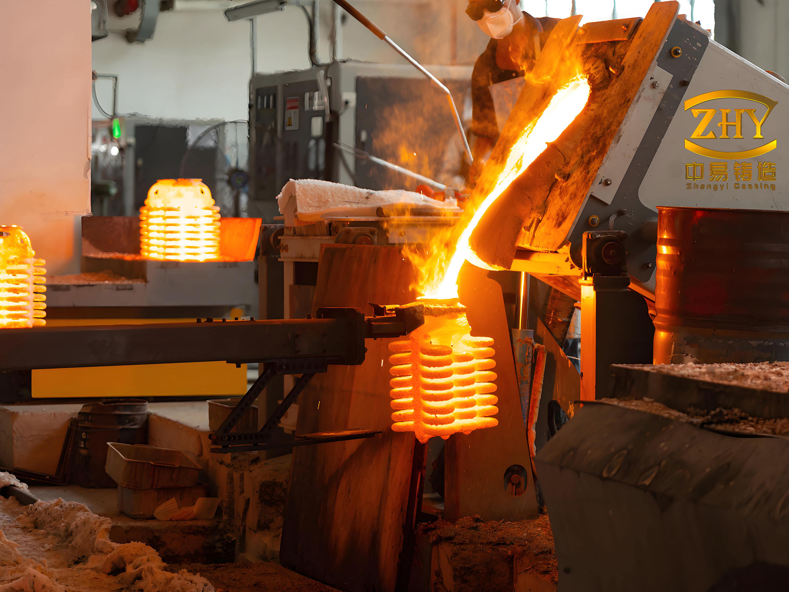
The image above illustrates a typical precision lost wax casting setup, highlighting the intricate shell and gating system. In my case, the initial design failed to maintain a continuous feeding path to the pump feet. To optimize the process, I redesigned the gating system to alter the solidification sequence. The key change was relocating Ingate 3 to directly feed the flow channel, which then feeds the pump feet, rather than trying to feed the feet separately. This created a sequential order: sprue → Ingate 3 → flow channel → pump feet. Additionally, I added a tie between risers for better thermal uniformity. The modified dimensions are summarized below.
| Component | Optimized Dimensions (mm) | Function |
|---|---|---|
| Sprue | 60 × 60 × 250 | Increased height for better head pressure |
| Ingate 3 (modified) | 160 × 60 × 40 | Now feeds flow channel directly |
| Tie (added) | 20 × 25 × 135 | Enhances riser connection and venting |
This redesign aimed to ensure that the pump feet remain connected to a feeding source until solidification completes. The modulus ratio for the new Ingate 3 relative to the flow channel was recalculated to be above 1.2, improving feeding efficiency. In precision lost wax casting, such adjustments are often iterative, but simulation accelerates the optimization.
I reran the ProCAST simulation with the optimized design. The filling sequence was similar, but now metal flowed through Ingate 3 into the flow channel earlier, promoting better thermal distribution. The complete filling time increased slightly to 16 seconds due to the larger ingate. The solidification simulation showed a marked improvement. The solid fraction evolution indicated that the pump feet now solidified after the flow channel, with Ingate 3 providing continuous feeding. No isolated liquid pools formed. The sequence was: pump feet solidifying first, fed by the flow channel, which in turn was fed by Ingate 3, while the flanges were fed by their respective ingates. The entire casting solidified directionally toward the risers, with the last point in the runner system. The shrinkage defect prediction was zero in the casting, with all defects confined to the gating system, as desired. The total solidification time was around 1,443 seconds.
To quantify the improvement, we can consider the Niyama criterion, often used to predict shrinkage porosity in steel castings. It is defined as:
$$ Niyama = \frac{G}{\sqrt{\dot{T}}} $$
where \( G \) is the temperature gradient and \( \dot{T} \) is the cooling rate. A higher Niyama value indicates lower risk of shrinkage. In the initial design, at the defect location, the Niyama value was below a critical threshold (e.g., 1 °C¹/²·s¹/²), while in the optimized design, it increased above that threshold due to better feeding. Although ProCAST uses more sophisticated criteria, this illustrates the principle. The table below compares key simulation outcomes.
| Aspect | Initial Design | Optimized Design |
|---|---|---|
| Filling Time | 15 s | 16 s |
| Total Solidification Time | ~1,600 s | ~1,443 s |
| Shrinkage Volume in Casting | 0.6 cm³ | 0 cm³ |
| Isolated Liquid Regions | Yes, at foot-channel junction | No |
| Directional Solidification | Partial | Fully achieved |
The optimized precision lost wax casting process was then implemented in production. Wax patterns were assembled according to the new design, ceramic shells were built, and CF8 stainless steel was melted and poured at 1,600°C. After shell removal and cleaning, the castings underwent non-destructive testing, including X-ray radiography and pressure testing. No internal defects were detected, and the castings met all quality requirements. This successful validation underscores the power of numerical simulation in precision lost wax casting optimization.
Beyond this specific case, the principles applied here are universally relevant for precision lost wax casting. The interaction between gating geometry, thermal modulus, and solidification kinetics is complex but manageable through simulation. For instance, the Chvorinov’s rule can estimate solidification time \( t \) for a section:
$$ t = B \left( \frac{V}{A} \right)^2 $$
where \( V \) is volume, \( A \) is surface area, and \( B \) is a molding constant. In precision lost wax casting, the ceramic shell has a high insulating effect, so \( B \) is larger than in sand casting, prolonging solidification and emphasizing feeding needs. Therefore, designing feeders with adequate modulus is crucial. Additionally, the role of pouring temperature and shell preheat can be analyzed using heat transfer coefficients. For example, the interfacial heat transfer coefficient \( h \) between metal and shell varies with conditions, affecting cooling rates. A simplified model for heat flux \( q \) is:
$$ q = h (T_m – T_s) $$
where \( T_m \) is metal temperature and \( T_s \) is shell temperature. In precision lost wax casting, controlling these parameters helps manage solidification.
In conclusion, my work on the CF8 stainless steel pump body demonstrates that precision lost wax casting, when combined with numerical simulation, can achieve defect-free complex castings. The optimization involved redesigning the gating system to ensure directional solidification and continuous feeding, eliminating shrinkage porosity. This approach not only improves quality but also reduces trial-and-error costs. The repeated emphasis on precision lost wax casting throughout this article highlights its significance in modern manufacturing. As industries demand higher performance components, the integration of simulation tools with traditional craftsmanship will continue to advance the art and science of investment casting.
To further elaborate, the success of precision lost wax casting relies on a deep understanding of material properties and process variables. For CF8 stainless steel, the solidification shrinkage is approximately 3-4%, which must be compensated by feeders. The feeding distance limits in precision lost wax casting are influenced by shell thickness and conductivity. Empirical rules suggest that for steel castings, the maximum feeding distance \( L_f \) can be estimated as:
$$ L_f = 4.5 \sqrt{t} $$
where \( t \) is wall thickness in mm. For a 30 mm flange, \( L_f \) is about 24.7 mm, implying close feeder placement. My initial design violated this near the pump feet due to geometric constraints, but the optimization effectively extended the feeding range through the flow channel. Moreover, the use of simulation allows for exploring multiple scenarios, such as varying pouring temperatures or shell materials, to further refine the process.
In future applications of precision lost wax casting, emerging technologies like additive manufacturing for wax patterns and advanced ceramic shells could enhance precision. However, the core principles of thermal management and feeding will remain. By sharing this case, I hope to emphasize that systematic analysis and simulation are indispensable for mastering precision lost wax casting, ensuring that every casting meets the highest standards of integrity and performance.