
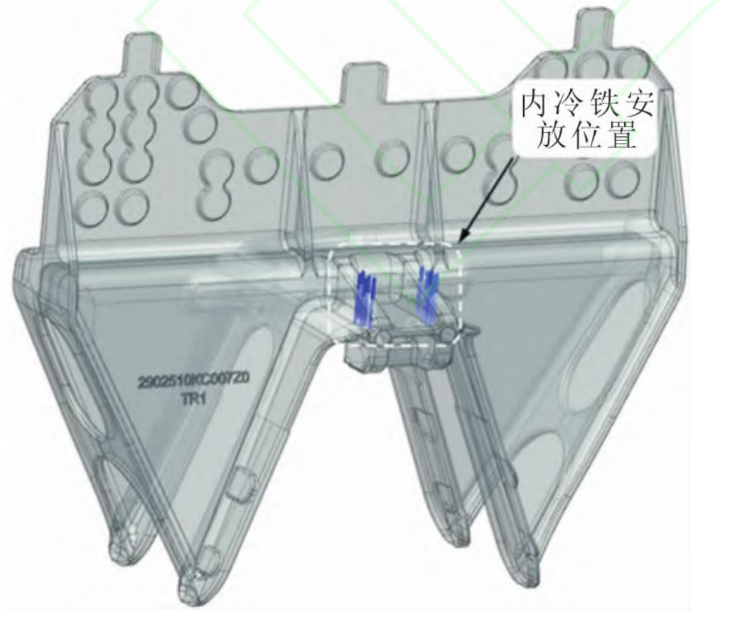
From the simulation of the solidification process in the initial plan, it can be seen that the saddle is prone to generate hot spots at the corner of the limit hook, leading to the final solidification at that position, forming an isolated liquid phase zone that does not comply with the principle of sequential solidification, and thus resulting in shrinkage porosity and porosity defects. Due to the complex structure and thin wall of the saddle, it is not possible to supplement the hot joint by setting a riser to eliminate defects. Therefore, in order to improve the overall quality of large thin-walled castings, without changing the pouring process, the method of local sequential solidification and overall balanced solidification of large thin-walled castings is adopted by placing internal cooling iron at the limit hook, Using the chilling effect of cold iron to increase the cooling speed at the hot spot [- S. The internal cold iron is made of high carbon steel, with circular nails with a diameter of 3 mm. Five circular nails are placed on each reinforcing rib, and their diameter is determined based on the size of the hot spot. A small cold iron cannot achieve cooling effect. A large cold iron may cause problems such as poor fusion. The placement position of the circular nails is shown in Figure 1.
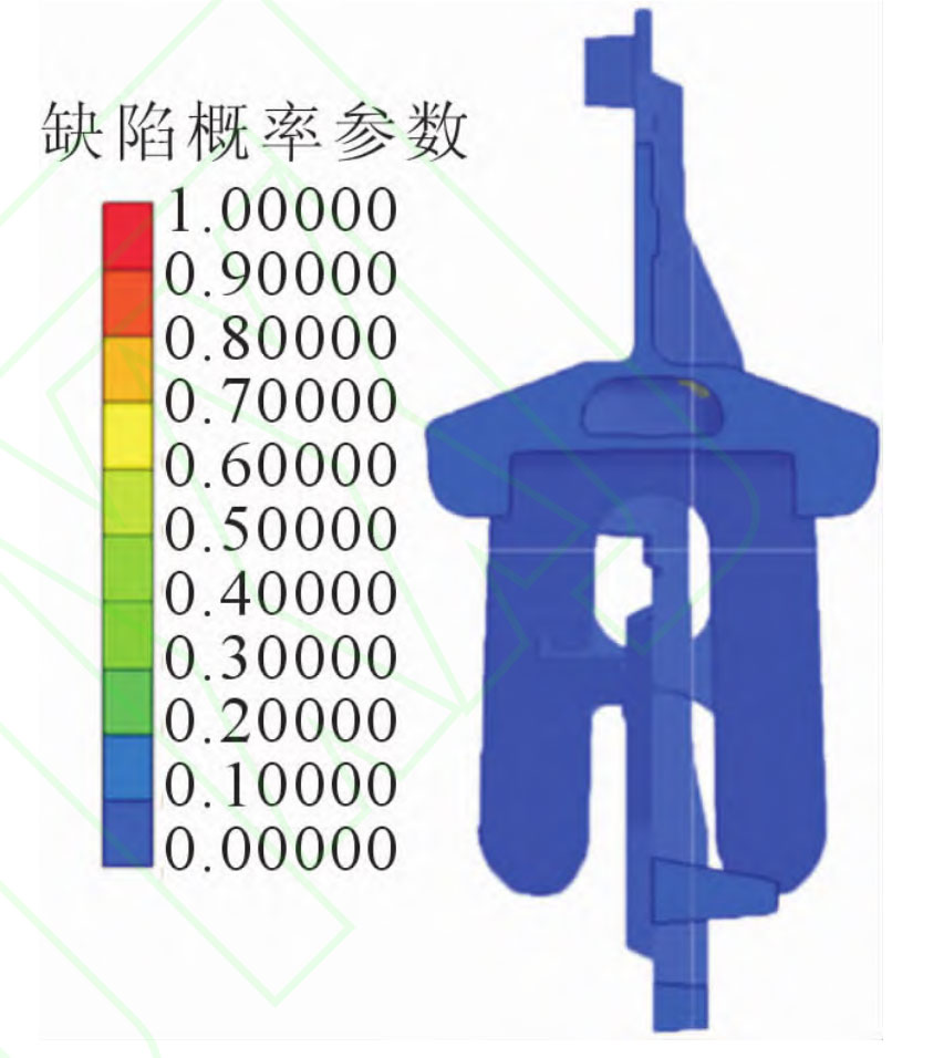
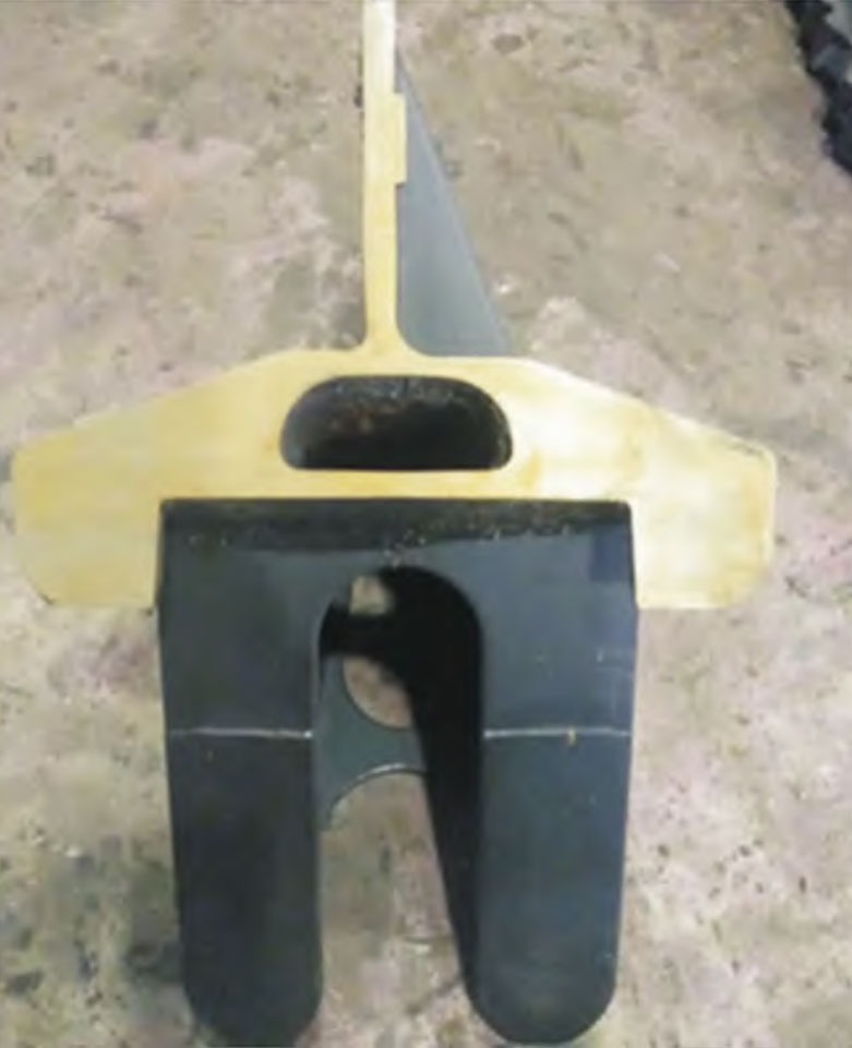
After optimizing the plan, the designed internal cooling iron plays a cooling role, allowing the hot spot position to solidify first, reducing the tendency of large thin-walled castings to produce isolated liquid phase zones, and effectively eliminating the hot spot at the limit hook. Figure 2 shows the distribution of defects in large thin-walled castings simulated by the final improvement plan. From the simulation results, it can be seen that the shrinkage porosity and shrinkage cavity defects at the limit hook device have been completely eliminated. On the basis of the optimized plan, trial casting experiments were conducted to cut and inspect large thin-walled castings. As shown in Figure 3, the disappearance of defects was consistent with the simulation results, proving the rationality of the optimized process plan. At the same time, the internal cooling iron and the poured molten iron have been fused into one, without any problem of poor fusion. The excess internal cooling iron is polished off by a grinder and can be used for actual production.
(1) A closed pouring system combining bottom injection and layered injection was designed using a non riser casting method, with a pouring time of 14 seconds. In order to ensure that the metal liquid quickly fills the large thin-walled casting cavity, 6 internal gates, 1 circular transverse gate, and 1 vertical gate were designed. To effectively discharge the metal liquid gas and avoid porosity defects, 3 exhaust holes were designed on the large thin-walled casting cavity, and 4 exhaust holes were designed at the edge of the sand core.
(2) The filling and solidification process was analyzed using AnyCasting simulation software. The simulation results showed that shrinkage porosity and porosity defects were mainly distributed at the limit hook position, with a total volume of 0.32 cm3. Through actual pouring, it was found that the actual defect location of the casting was consistent with the simulation results, proving the credibility of the simulation results.
(3) Adopting the addition of internal cooling iron for process optimization, the corner hot spot position is solidified first, reducing the tendency of large thin-walled castings to produce isolated liquid phase zones, effectively eliminating shrinkage porosity and shrinkage defects in large thin-walled castings, and consistent with the actual pouring results.