
For the stepped pouring scheme, the pouring temperature of 1400 “C and the pouring speed of 6.8kg/s are the most appropriate. According to the analysis, in order to alleviate the impact of the stepped pouring system on the lower transverse sprue and increase the feeding effect of the riser set at the upper end of the tractor box sand casting, this chapter improves the original stepped Pouring Scheme and the structure of the tractor box sand casting respectively.
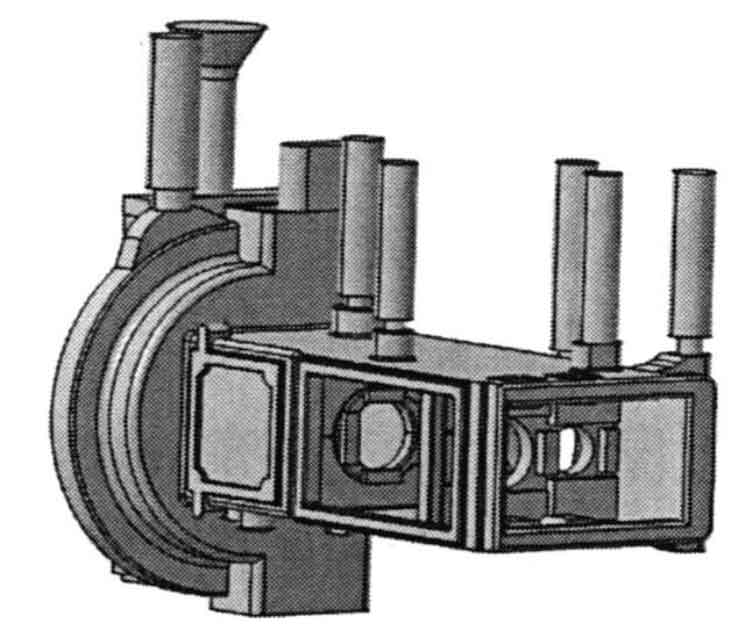
For the stepped pouring scheme, this chapter increases the diameter of the riser at the arc boss and the upper riser of tractor box sand castings; A riser is added at the convex block at the upper end of the rectangular boss and tractor box sand casting; A buffer zone shall be set at the connection between the lower transverse sprue and the direct sprue; And add cold iron at the support plate inside the box; The improved scheme of gating system is shown in Figure 1.
(b) Ladder scheme improvement diagram
(b) Scheme IV
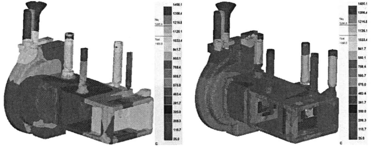
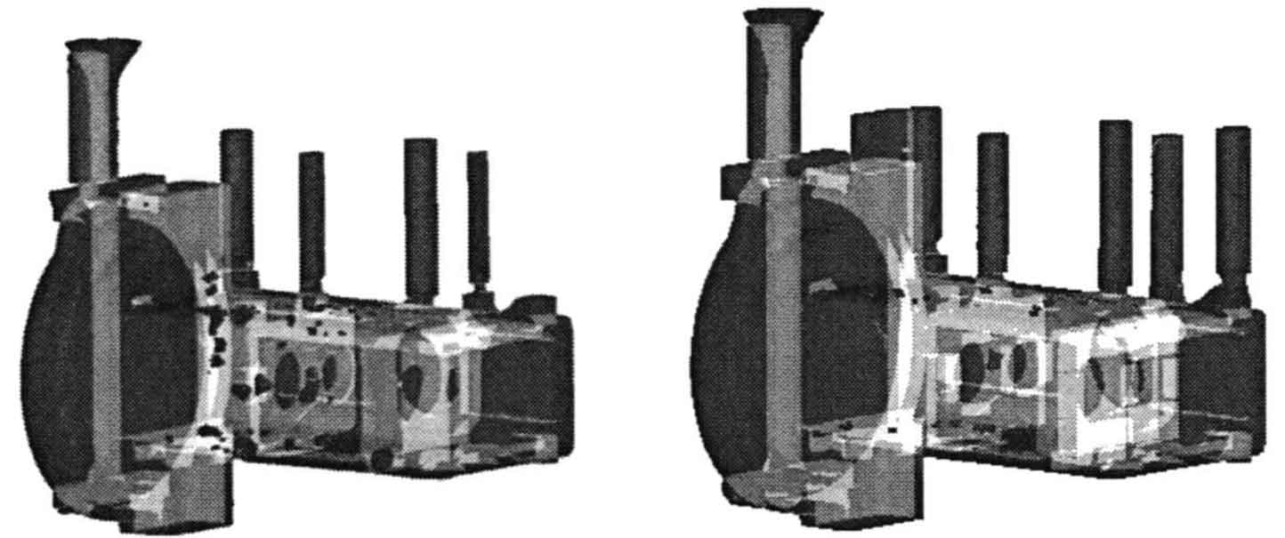
For the improved step pouring scheme, the pouring temperature is set at 1400. C. The pouring speed is 6.8kg/s, and other parameters remain unchanged. Figure 2 shows the comparison of solidification process between the original step scheme and the improved step scheme. Compared with the original stepped scheme, the solidification effect of the improved position in the improved stepped scheme is improved, and the feeding capacity of the riser liquid metal at the arc boss is increased by J / 11; The riser added on the rectangular boss plays the role of feeding, which makes the rectangular boss realize sequential solidification, and the final solidification position is the added riser; The riser at the upper end of tractor box sand casting also plays a role in feeding due to the increase of size; The riser added at the boss at the upper end of the tractor box sand casting makes the last solidification position of the upper end of the tractor box sand casting extend to the riser, which plays a good role in feeding and reduces the occurrence of defects. Figure 3 shows the comparison of shrinkage cavity and porosity defects between the original stepped scheme and the improved stepped scheme. The defects of the improved stepped scheme are significantly reduced.
According to the structure of the reducer case body casting, the structural analysis of the tractor case sand casting shows that the fillet radius of the intersection of the two walls of the rectangular boss and the arc boss is 17mm, and there is a hot spot; The fillet radii between the two intersecting walls of the circular arc boss are 5mm, 6mm and 14mm respectively. There are also hot spots at the connection between the flat plate and the boss on both sides of the tractor box sand casting; Through the simulation of the stepped scheme, it is found that the flow direction of liquid metal changes greatly at these positions, which is easy to cause entrainment; There is a sudden change of wall thickness at the support plate under the interior of tractor box sand casting, so it is easy to cause defects.
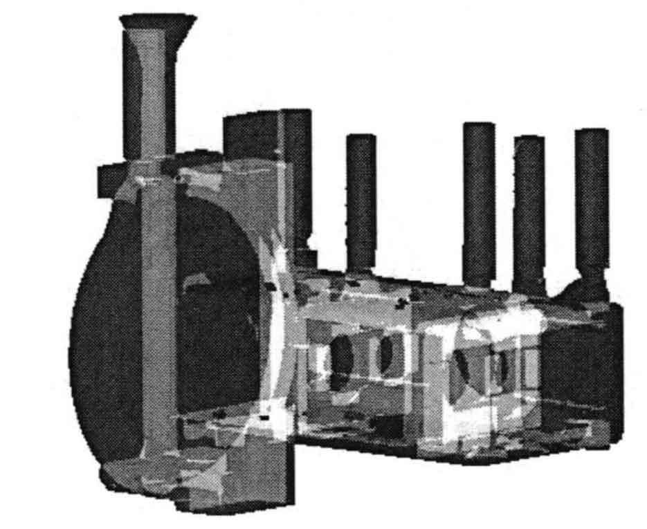
Therefore, the structure of tractor box sand castings is locally improved. On the basis of the improved stepped scheme, the fillet radii between the two-phase walls of the circular arc boss are increased from 5mm, 6mm and 14mm to 10mm, 12mm and 20mm; Increase the fillet radius of the intersection of the two walls at the rectangular boss and the circular boss from 17mm to 30mm; The thin wall of the inner lower support plate of tractor box sand casting was increased from 10mm to 15ram, and the thick wall was reduced from 30mm to 25mm.
Then set the pouring temperature 1400. C. The pouring speed is 6.8kg/s, and other parameters remain unchanged. Through the simulation analysis of the stepped scheme of the improved structure of tractor box sand casting, it is found that by changing the size of the fillet, the hot spot at the fillet can be avoided and the defects at the intersection of the two walls can be reduced; Changing the size of the internal support plate reduces the defects of the support plate caused by uneven wall thickness. The defect diagram after solidification is shown in Figure 4.