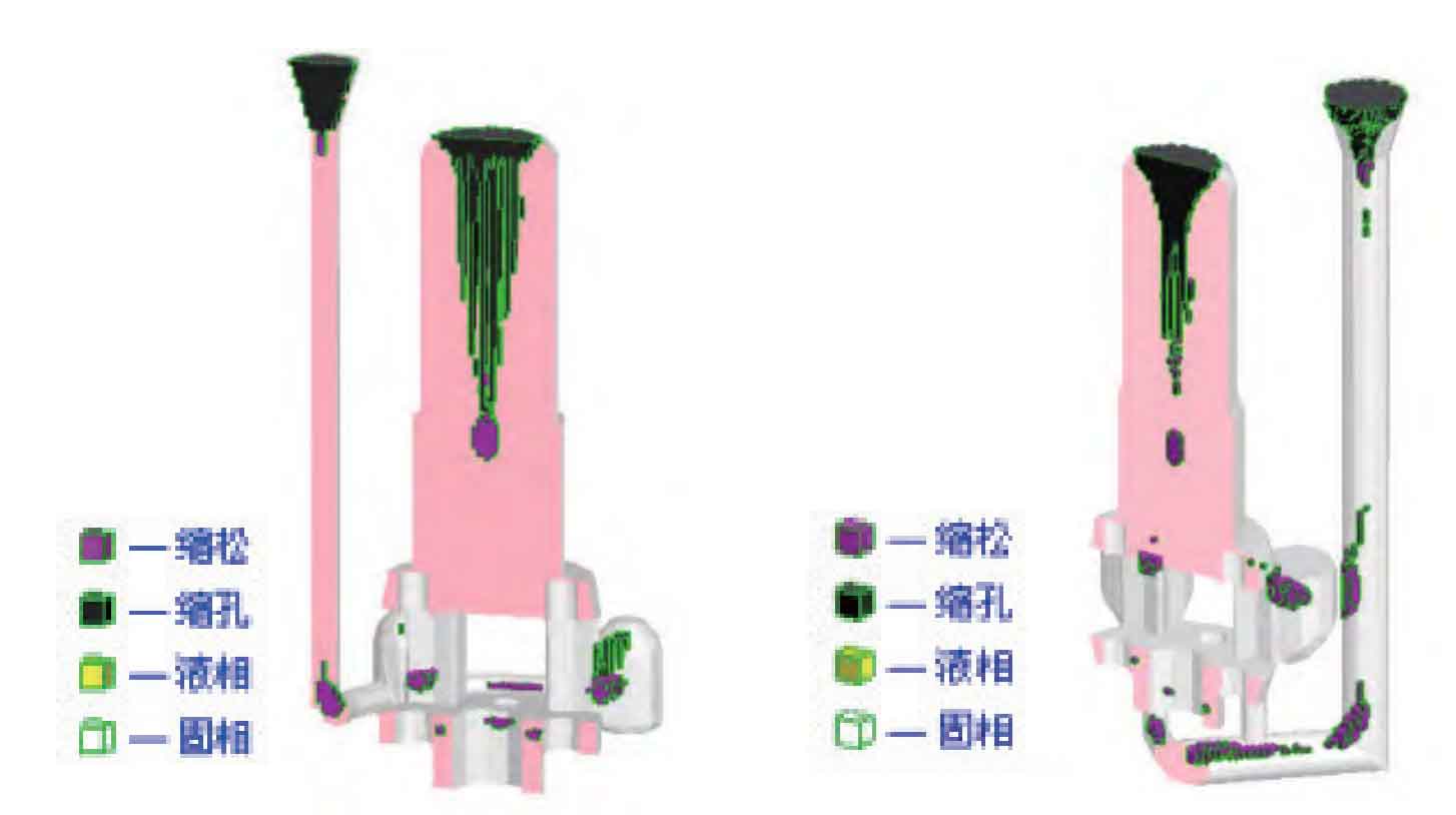
(1) The casting process plan determines that the casting adopts the whole sample sand box molding production mode. According to the structural characteristics of the casting, considering the advantages of molding operation, the parting surface is set at the plane of the intersection between the upper cylinder and the lower part of the planet carrier, with the cylinder facing upward.
(2) Main process parameters
1) Casting shrinkage: the internal structure of the planet carrier housing is complex, and the wall thickness difference is large. The overall casting shrinkage is 2.0%.
2) Machining allowance: according to the casting manual, according to the maximum size of the casting and referring to previous production experience, the machining allowance of the casting is determined to be 15mm above, 10mm below, 13mm at the side and 13mm at the shaft hole.
(3) For modification of wood formwork, remove all the old wood formwork riser platforms, and make riser platforms and subsidies according to the location and size of the changed drawing. The uniform thickness of riser locating plates is 15~18mm, and the riser platforms and the surrounding fillets of subsidies are made according to R30mm. Check all the sand attached surfaces of the external mold and core box, and repair all the defects such as paint falling off, cracking and sanding.
(4) In order to ensure the quality and dimensional accuracy of the planet carrier casting, the casting sand mold and sand core are made of resin sand. The surface of the sand mold shall be painted with alcohol based zircon powder paint for three times, and the parts easy to stick with sand shall be painted twice more to ensure smoothness and uniformity. A proper amount of chromite ore sand shall be placed at the sand mold parts easy to stick and the rounded corners.
(5) The riser design uses Proe 3D drawing software to make 3D drawing of the planet carrier. According to the previous production experience, the feeding area of the planet carrier shell is preliminarily divided, and each feeding area corresponds to a riser for feeding. The riser modulus is determined by the size of the hot spot at the feeding part of the riser. Finally, 4 insulation concealed risers and 1 insulation exposed riser are determined to be used.
(6) Casting simulation According to the preliminarily determined casting process plan, the shape, size and position of different risers used for the planet carrier, the number and position of the gating system, and the number and placement position of the cold iron were simulated, analyzed and verified respectively.
1) Simulation scheme 1: the simulation results are shown in Figure 1. The simulation shows that the quality of the castings produced by this plan is much better than that of the castings produced by the original process plan. There are no obvious macro defects such as large-area porosity and shrinkage cavity, but there are still 14 minor defects such as porosity and 94 shrinkage cavities.
2) Simulation scheme 2: in simulation scheme 2, the side pouring is changed into the bottom pouring, and the simulation results are shown in Figure 2. The simulation shows that the quality of the castings produced by this plan is significantly improved compared with that of the castings produced by the original process plan, and there are no obvious macro defects such as large-area porosity and shrinkage cavity. Compared with the casting of simulation 1, the shrinkage cavity is significantly reduced, but the micro porosity is significantly increased.

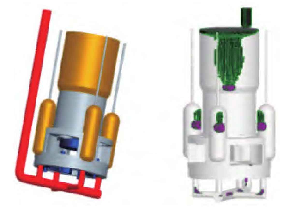
3) Simulation scheme 3: comprehensively analyze the problems in simulation scheme 1 and simulation scheme 2, optimize the casting process, and form the final process scheme through analysis, calculation and verification by simulation software. The simulation results are shown in Figure 6. It can be seen from Figure 3 that the feeder feeding meets the casting quality requirements, and then further refine the simulation to minimize the size of the feeder, so as to reduce the cost, and finally determine the quantity and size of the feeder and the external chill.

(7) According to the structural characteristics of the casting, the pouring system adopts a bottom reverse type pouring system to make the molten steel rise steadily, so as to avoid turbulence and ensure the internal quality of the casting. The gating system is designed as an open type to achieve the goal of rapid pouring, so as to reduce the surface cracking and falling off of the mold caused by long time exposure to the heat of molten steel radiation, as well as the defects such as sand inclusion, cracks and sand inclusion caused by local overheating and sand washing. All gating systems consist of ceramic tubes.
