
As an engineer involved in the production of wear-resistant stainless steel components, I have long been challenged by the complex geometry of pulping rotors used in the papermaking industry. These rotors must withstand high centrifugal forces, abrasive pulp slurry, and corrosive environments, which demand both excellent mechanical properties and precise dimensional accuracy. In my recent work, I focused on developing a casting process that leverages 3D printing sand casting technology, combined with numerical simulation, to produce a high-quality pulping rotor made of ZG06Cr13Ni4Mo martensitic stainless steel. This article presents my research findings, process optimization, and validation results, demonstrating that 3D printing sand casting offers significant advantages over traditional wooden mold methods for this type of complex component.
1. Introduction and Technical Requirements
The pulping rotor is a critical rotating component in paper pulping equipment. It operates at high speeds, generating strong centrifugal forces that throw the pulp slurry against impact plates, blades, and gear discs, thereby defibering the material into smaller particles. The rotor also induces a water-scrubbing action to further refine the pulp. Given these demanding operating conditions, the rotor material must possess high strength, excellent wear resistance, and good corrosion resistance. ZG06Cr13Ni4Mo, a medium-to-high-strength martensitic stainless steel, has been widely adopted in hydroelectric, petrochemical, and aerospace applications, and is increasingly used in the pulp and paper sector.
The technical specifications for the rotor casting are strictly defined by the standard GB/T 6967—2009. The required chemical composition is summarized in Table 1.
| Element | Minimum / Maximum |
|---|---|
| C | ≤ 0.06 |
| Si | ≤ 0.80 |
| Mn | ≤ 1.00 |
| S | ≤ 0.035 |
| P | ≤ 0.025 |
| Cr | 11.5 – 13.5 |
| Ni | 3.5 – 5.0 |
| Mo | 0.4 – 1.0 |
In addition to composition, the rotor must meet the mechanical property requirements listed in Table 2. Furthermore, the internal soundness of the casting must satisfy ultrasonic inspection class 2 of ASTM A609-12. These stringent requirements demand a highly controlled casting process and a robust feeding system to eliminate shrinkage porosity and other internal defects.
| Property | Value |
|---|---|
| Yield strength \( R_{p0.2} \) (MPa) | ≥ 550 |
| Tensile strength \( R_m \) (MPa) | ≥ 750 |
| Elongation \( A_5 \) (%) | ≥ 15 |
| Reduction of area \( Z \) (%) | ≥ 35 |
| Impact energy \( KV \) (J) | ≥ 50 |
| Hardness (HBW) | 221 – 294 |
2. Structural Characteristics of the Rotor
The pulping rotor I worked with has an outer diameter of 945 mm, a height of 158 mm, and a mass of approximately 156 kg. The rotor features a central disc structure with eight blades arranged around the outer circumference. The blades have a streamlined shape, which is critical for the dynamic balancing of the rotating assembly. The dimensional tolerance of these blades is extremely strict, as any deviation can cause excessive vibration during operation, leading to premature failure. The rotor is designed with an internal hollow cavity to reduce weight and inertia, as shown schematically in the cross-sectional view (not reproduced here for brevity).
Traditionally, this rotor would be produced using a wooden mold. However, the complex blade geometry makes wooden mold fabrication extremely difficult, time-consuming, and expensive. The minimum lead time for the wooden mold is 20 days, and the cost can reach tens of thousands of yuan. In contrast, 3D printing sand casting allows me to directly import the CAD model into a 3D sand printer and produce the mold in just one day, eliminating the mold-making cost entirely. Moreover, the 3D printing sand casting process does not require draft angles, which simplifies the molding and core-assembly operations. This is particularly advantageous for a geometrically complex component like the pulping rotor.
3. Casting Process Design
3.1 Shrinkage Allowance and Machining Allowance
Since the rotor is made of ZG06Cr13Ni4Mo martensitic stainless steel, the solidification shrinkage is significant. I applied a casting shrinkage allowance of 2.0%. The machining allowances were set as follows: 8 mm on the top surface, 10 mm on the outer circumference, 6 mm on the bottom surface, and the central shaft hole was not cast. The final rough casting mass was calculated to be 187 kg.
3.2 Gating System Design
I designed a bottom-gating system with an ingate diameter of 60 mm. The molten steel enters the mold cavity from the bottom and rises smoothly upward to the risers. This arrangement promotes a quiescent fill, allowing gases and inclusions to float up into the risers, thereby improving the internal cleanliness of the casting. The pouring temperature was controlled at 1560–1580 °C, and the bottom-pour ladle was equipped with a 50 mm nozzle. Before pouring, the steel was allowed to settle in the ladle for more than 5 minutes to facilitate the floatation of oxides and slag.
3.3 Riser Design and Optimization
To feed the solidification shrinkage effectively, I placed a cylindrical riser of φ200 mm × 280 mm in the center of the rotor. The riser modulus was 4.5 cm. At the root of the teeth (blades), I installed eight insulating risers with dimensions of φ70 mm × 100 mm, each having an effective modulus of 1.8 cm. Additionally, an exhaust riser of φ20 mm was placed at the outer end of each blade to vent gases. The total liquid steel weight, including the gating and risering system, was 312 kg. The complete casting layout is shown in the process diagram (omitted here).
To verify and optimize the riser design, I performed solidification simulations using the Procast software. The three-dimensional finite element mesh was generated, and the material properties of ZG06Cr13Ni4Mo were assigned. The boundary conditions assumed a heat transfer coefficient of 500 W/(m²·K) at the mold-metal interface, an initial pouring temperature of 1580 °C, an ambient temperature of 25 °C, a pouring time of 6 seconds, and a pouring rate of 50 kg/s. The cooling was set to air cooling. The simulation results predicted the temperature distribution during solidification and the location of potential shrinkage defects. Based on these predictions, I refined the riser dimensions and placement to ensure adequate feeding throughout the casting.
The feeding distance and modulus calculation can be expressed using Chvorinov’s rule:
$$ t_f = B \left( \frac{V}{A} \right)^2 $$
where \( t_f \) is the solidification time, \( B \) is a mold constant, \( V \) is the volume, and \( A \) is the cooling surface area. The modulus \( M \) is defined as \( V/A \). For the rotor, I ensured that the riser modulus was larger than the casting modulus in the feeding zone. The required riser modulus was calculated as:
$$ M_{riser} \geq 1.2 \, M_{casting} $$
For the central hub, the casting modulus was 3.75 cm, so the riser modulus of 4.5 cm satisfied this criterion with a safety factor of 1.2. For the blade roots, the local modulus was 1.5 cm, and the 1.8 cm modulus of the insulating risers provided sufficient feeding.
3.4 3D Printing Sand Mold Design
The sand molds were produced using a VX2000 3D sand printing machine. The printing material was GS15 type silica sand, with a 3DP-specific resin binder and a corresponding curing agent. The maximum printable mold size was 2000 mm × 1000 mm × 1000 mm. The layer thickness was 0.3 mm, and the printing time per layer was less than 32 seconds. The dimensional accuracy of the printed sand mold was within ±0.3 mm. The resin addition was 1.2%, and the curing agent addition was 0.3%, resulting in a sand mold strength of 1.4 MPa. This strength was sufficient to withstand the ferrostatic pressure during casting without deformation.
The upper and lower sand molds were printed separately. The 3D printing sand casting process eliminated the need for separate core boxes, as the internal cavities were printed directly. The mold assembly was straightforward, and the alignment accuracy was exceptionally high. The printed lower sand mold is shown in Figure 1, and the upper sand mold in Figure 2. The following figure illustrates the general principle of 3D sand printing:
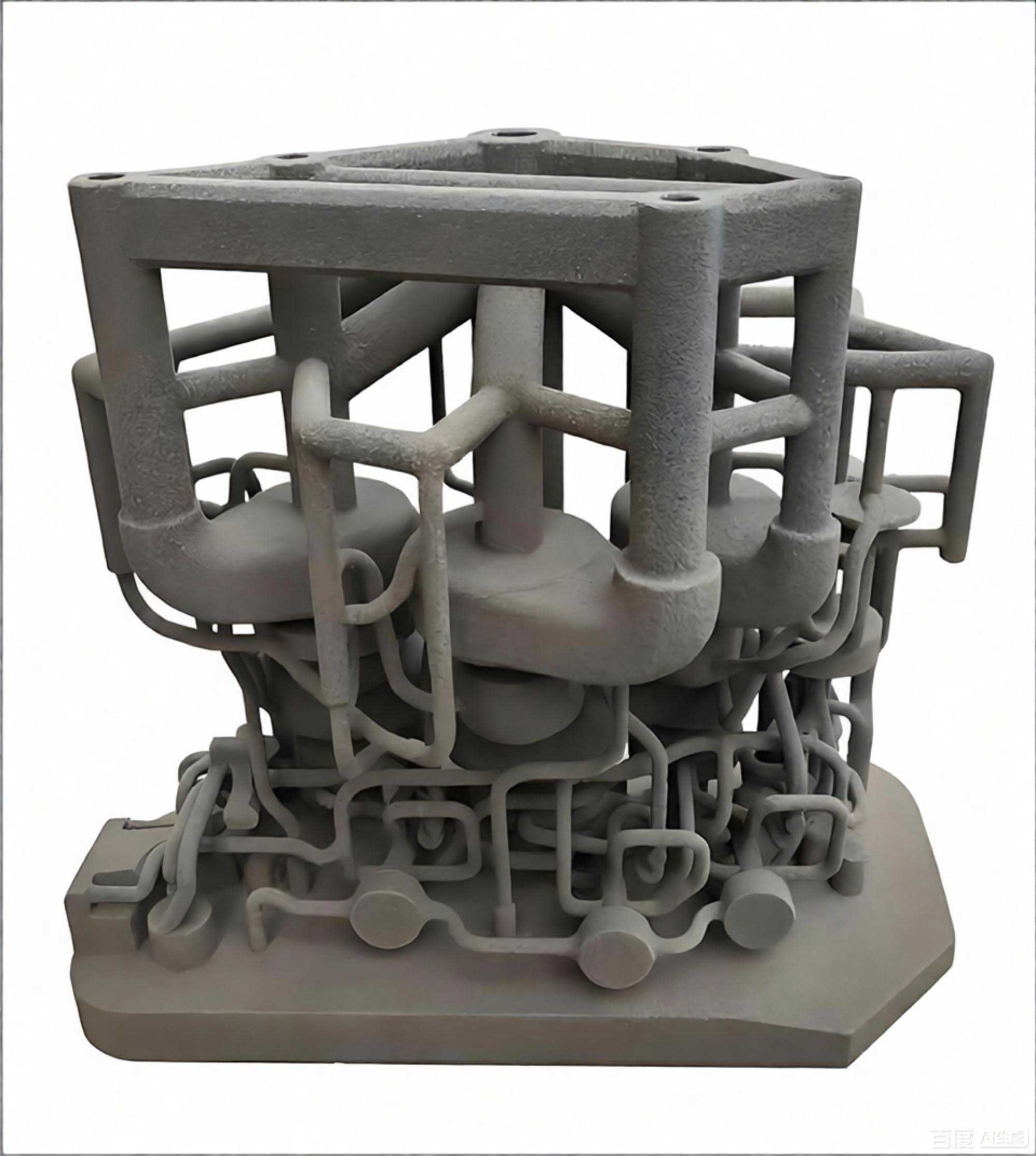
The use of 3D printing sand casting brought several key advantages. First, the mold compactness was uniform throughout, unlike rammed wooden molds where density can vary. Second, the ability to print freeform internal channels allowed me to optimize the gating and risering system more flexibly. Third, the elimination of draft angles meant that the blade surfaces were produced with true geometry, reducing the need for subsequent machining and improving the overall dimensional accuracy.
4. Melting and Heat Treatment
The steel was melted in an alkaline electric arc furnace and refined in an AOD (Argon Oxygen Decarburization) vessel. This duplex melting process was essential to achieve the low carbon content required for the martensitic stainless steel. I strictly controlled the carbon content to below 0.03% to ensure good weldability and impact toughness. Phosphorus and sulfur were also kept at minimal levels to avoid hot cracking and improve ductility.
After casting, the rotor was subjected to heat treatment consisting of normalizing followed by tempering. The normalizing temperature was (1020 ± 10) °C with a holding time of 2 hours. The tempering temperature was (600 ± 10) °C with a holding time of 4 hours. The heating rates were carefully controlled: when the furnace temperature was between 300 and 600 °C, the heating rate did not exceed 100 °C/h; when the furnace temperature was between 600 and 1020 °C, the heating rate did not exceed 80 °C/h. These controlled heating rates minimized thermal stresses and avoided distortion.
5. Simulation Results and Defect Prediction
The Procast simulation provided valuable insights into the solidification behavior of the rotor. The temperature distribution at the end of solidification is shown in a contour plot (not reproduced here). The simulation revealed that the last solidified regions were in the central riser and the blade-root regions, which were adequately fed by the risers. The shrinkage porosity prediction indicated that no significant defects exceeding the acceptance criteria would form. The isolated hot spots that were initially observed near the blade roots were successfully eliminated by adding the eight insulating risers. The final feeding system achieved a process yield of 60%, which is calculated as:
$$ \eta = \frac{m_{casting}}{m_{casting} + m_{risers} + m_{gating}} \times 100\% = \frac{187}{312} \times 100\% \approx 60\% $$
This yield is quite satisfactory for a complex stainless steel casting. The simulation also allowed me to optimize the pouring parameters, ensuring a smooth and turbulence-free filling of the mold cavity.
6. Experimental Validation
After the casting was shaken out, the risers and gating system were cut off, and the rotor was subjected to sand blasting. I then performed a series of inspections to verify the quality of the final product.
6.1 Dimensional Inspection
Using a layout platform, I marked and measured the eight blades of the rotor. All blades were found to have consistent heights, and the dimensions were within the required tolerances. The blade geometry was accurate, confirming that the 3D printing sand casting process eliminated the draft-angle distortion that often occurs with wooden molds. The dimensional deviation of the blades was less than ±0.5 mm, which is excellent for a casting of this size.
6.2 Ultrasonic Testing
Ultrasonic inspection was performed according to ASTM A609-12. The entire volume of the rotor was scanned, and no indications exceeding the class 2 acceptance level were found. This confirmed that the casting was free of harmful shrinkage, porosity, and inclusions. The simulated defect predictions were in good agreement with the actual inspection results, validating the reliability of the Procast simulation in predicting casting quality.
6.3 Chemical Composition and Mechanical Properties
I took specimens from the casting and analyzed the chemical composition. The results, shown in Table 3, met all the requirements of the specification.
| Element | Measured value | Requirement |
|---|---|---|
| C | 0.028 | ≤ 0.06 |
| Si | 0.52 | ≤ 0.80 |
| Mn | 0.78 | ≤ 1.00 |
| S | 0.008 | ≤ 0.035 |
| P | 0.012 | ≤ 0.025 |
| Cr | 12.5 | 11.5 – 13.5 |
| Ni | 4.2 | 3.5 – 5.0 |
| Mo | 0.65 | 0.4 – 1.0 |
Tensile and impact tests were performed on specimens machined from the casting. The measured mechanical properties are presented in Table 4. All values exceeded the minimum requirements, demonstrating that the heat treatment produced the desired martensitic structure with a good balance of strength and toughness.
| Property | Measured value | Requirement |
|---|---|---|
| Yield strength \( R_{p0.2} \) (MPa) | 720 | ≥ 550 |
| Tensile strength \( R_m \) (MPa) | 890 | ≥ 750 |
| Elongation \( A_5 \) (%) | 18 | ≥ 15 |
| Reduction of area \( Z \) (%) | 42 | ≥ 35 |
| Impact energy \( KV \) (J) | 68 | ≥ 50 |
| Hardness (HBW) | 270 | 221 – 294 |
6.4 Cost and Lead Time Comparison
One of the most compelling reasons for adopting 3D printing sand casting is the economic benefit. For my specific rotor, the volume of the printed sand mold was 0.48 m³, and the cost of the 3D printing sand was approximately 0.35万元 per cubic meter. Therefore, the total material cost for the sand mold was only 0.168万元. In contrast, the wooden mold for the same rotor was estimated to cost about 3万元. For a single piece or small batch production, the cost savings are substantial. Furthermore, the lead time was reduced from at least 20 days for the wooden mold to just 1 day for the 3D printed sand mold. This speed is invaluable in prototype development and emergency replacement parts.
I also observed that the 3D printing sand casting process reduced the need for skilled molders, as the mold joining and core assembly were simpler. The uniform sand strength prevented mold erosion and minimized the risk of sand inclusions. All these factors contributed to a higher first-pass yield and lower overall production cost.
7. Conclusions and Outlook
Based on my practical experience with this pulping rotor, I can draw the following conclusions:
- The use of Procast simulation was instrumental in verifying the casting process and optimizing the riser dimensions. The final process achieved a yield of 60% without compromising the soundness of the casting. The predicted shrinkage defects were successfully eliminated by adding insulating risers at the blade roots.
- 3D printing sand casting proved to be a superior alternative to traditional wooden mold casting for the complex pulping rotor. The production cycle was dramatically shortened from 20 days (for wood pattern) to 1 day (for 3D printed sand mold). In terms of cost, the 3D printed sand mold cost only 0.168万元 compared to 3万元 for the wooden mold, making it far more economical for single-piece or small-batch production.
- The dimensional accuracy of the blades was significantly improved with 3D printing sand casting because the mold compactness is uniform and no draft angle is required. The blade height deviation was within ±0.5 mm, which is critical for the dynamic balance of the rotor.
- The quality of the final casting fully met the chemical, mechanical, and ultrasonic inspection requirements. This confirms that 3D printing sand casting is a reliable and efficient manufacturing route for high-alloy stainless steel components with complex geometries.
Looking forward, I believe that 3D printing sand casting will be increasingly adopted in the production of papermaking equipment and other heavy industrial components. The ability to combine topologically optimized designs with rapid mold production opens new possibilities for lightweighting and performance enhancement. For the pulping rotor specifically, further weight reduction could be achieved by designing internal lattice structures that can only be manufactured with 3D printing. The synergy between 3D printing sand casting and advanced simulation tools will continue to drive innovation in the foundry industry, enabling faster development cycles, lower costs, and higher quality castings.
In conclusion, my work has demonstrated that the integration of 3D printing sand casting with Procast simulation is a powerful approach for manufacturing complex stainless steel castings. The technique not only overcomes the limitations of traditional wooden molds but also meets the stringent quality requirements of modern industrial applications. I am confident that this technology will play a pivotal role in the future of casting production.