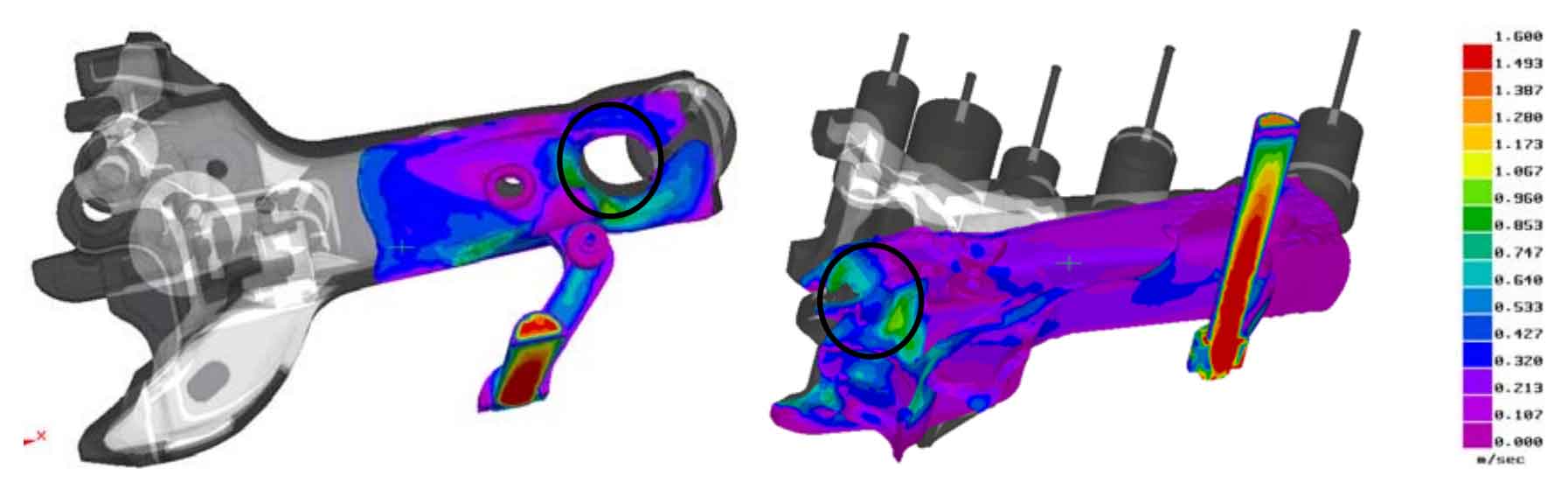
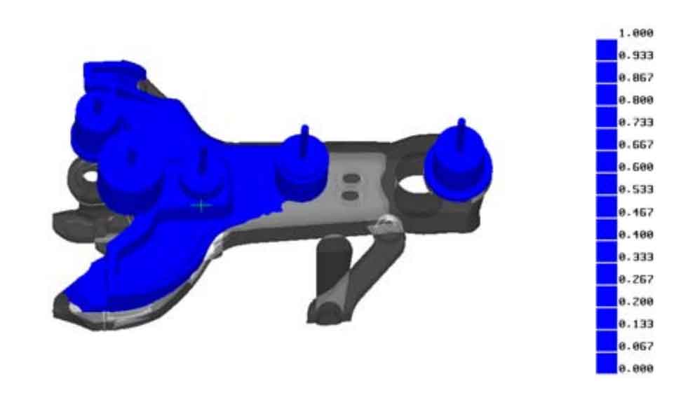
The improved process scheme is adopted for the hook body steel casting to simulate the mold filling and solidification process. The interface heat transfer coefficient between the insulation riser and the sand mold is 100W / (M2 · K), and other settings remain unchanged. During the mold filling process, it can be seen from Figure 1 that at the initial stage of pouring, the flow rate of liquid steel around the coupler tail pin hole is smaller and more uniform than that of the original process, which is conducive to avoiding erosion. When liquid steel enters the coupler head, the speed slows down. In the process, the erosion can also be avoided by increasing the sand strength and surface quality of the parts easy to be scoured (brushing fire-resistant coating); Figure 2 shows the prediction results of trapped gas. There is no trapped gas on the large plane of the hook body.
In the solidification process, Fig. 3 is the observation of the feeding effect of the riser through the longitudinal section distribution of the independent liquid phase area. The feeding channel at the riser is unobstructed and the feeding effect is obvious; Figure 4 shows the prediction of the position of the hot spot through the independent liquid phase area. The structure of the hook head is complex, the wall thickness is uneven, and the cooling shrinkage is inconsistent. There are independent liquid phase areas at the inner and outer corners of the hook head, the root of the traction table in the hook cavity and the corners of the hook shoulder, which are easy to form hot spots and eventually produce shrinkage porosity and thermal cracks, and the distribution is better than the original process; Figure 5 shows the prediction of shrinkage porosity. Except for a small amount of shrinkage porosity in the inner corners of the hook head, most of the shrinkage porosity is concentrated in the pouring and riser system, and the design of the pouring and riser system is more reasonable and effective than the original process.
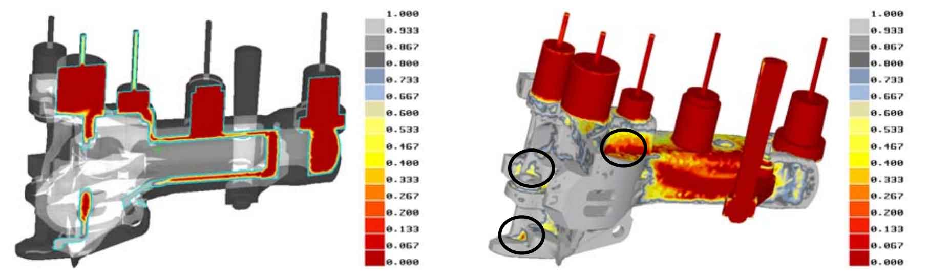
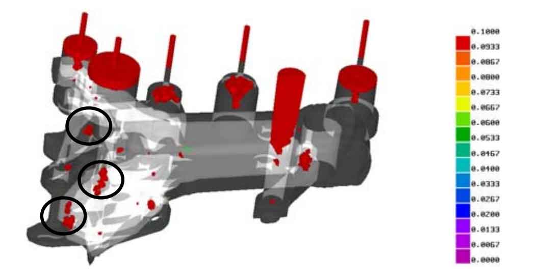
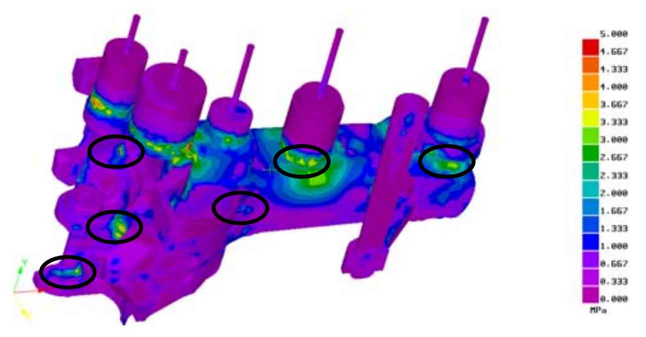
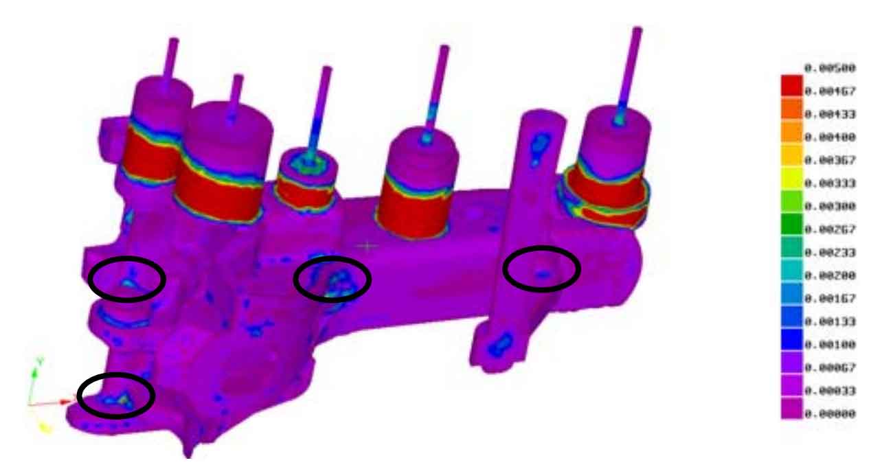
Fig. 6 and Fig. 7 are the stress field simulation results of the improved and optimized process. Figure 7 shows the equivalent stress distribution. It can be seen from the figure that the stress level is significantly lower than that of the original process, and the parts with large stress are still mainly the riser root, the corner of hook body and hook head and the corner of complex surface inside the hook head. Figure 8 shows the prediction results of hot crack tendency. The possible parts of hot crack are basically consistent with the parts with large equivalent stress, especially at the transition corner of hook body and hook head. Attention should be paid to later processing.