
In my extensive experience with casting high-performance engine parts, I have encountered numerous challenges related to defect formation in complex geometries. One particularly demanding project involved the production of a thin-walled exhaust connecting pipe made from silicon-molybdenum nodular cast iron. This component is critical in modern engine systems, and its quality directly impacts performance and durability. The initial production run revealed severe issues with shrinkage porosity and sand erosion defects, leading to an unacceptable scrap rate of approximately 38%. This article details my first-hand journey in diagnosing these problems and implementing a comprehensive solution strategy that successfully reduced defects to below 2% while simultaneously improving the process yield by 9.6%. The insights gained are broadly applicable to the casting of similar thin-walled structures in nodular cast iron.
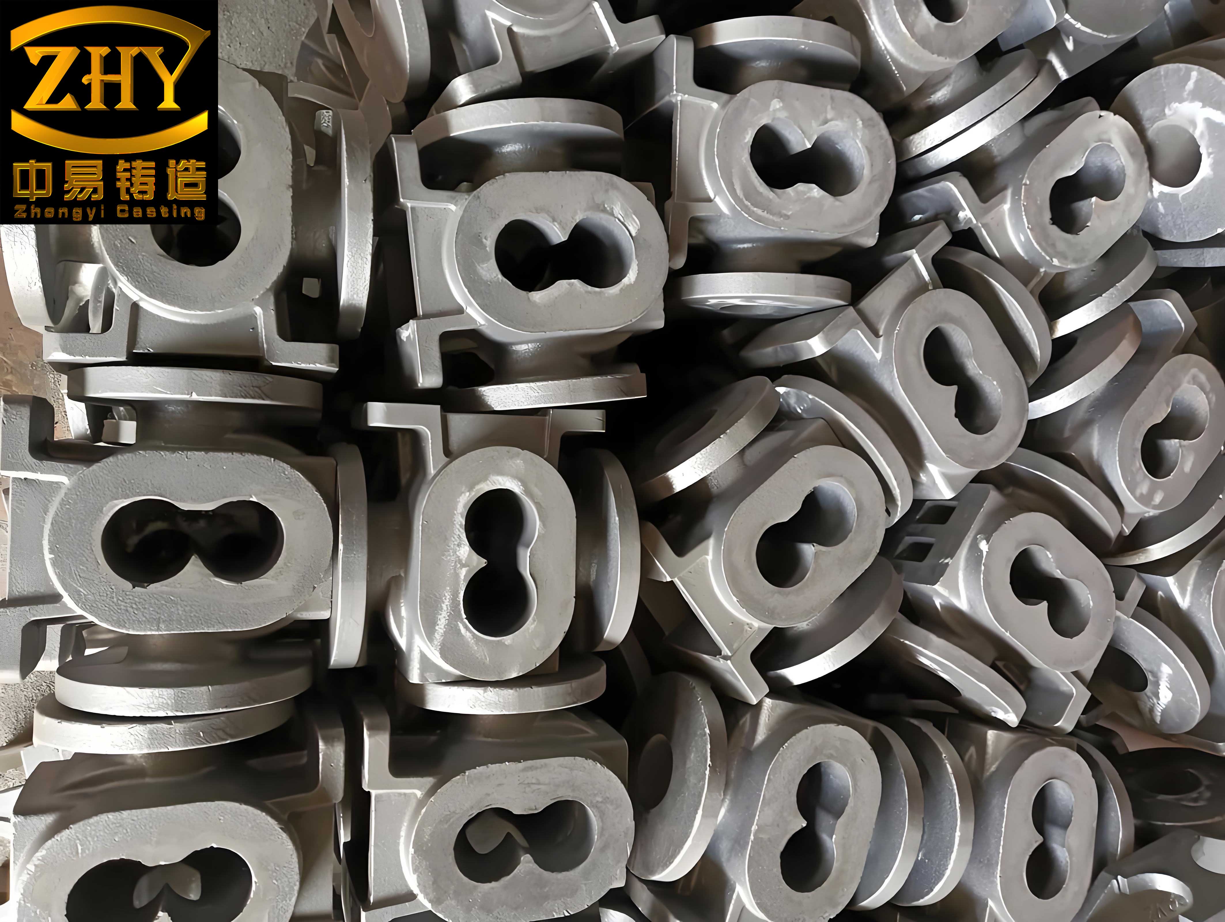
The exhaust manifold component in question is characterized by its intricate shape and varying wall thicknesses. The primary material is a silicon-molybdenum alloyed nodular cast iron, specified as QTRSi4Mo1. This grade of nodular cast iron is chosen for its excellent high-temperature strength and oxidation resistance, which are essential for exhaust applications. The casting’s nominal weight is 5.45 kg, with a major wall thickness of only 4.5 mm, making feeding and solidification control exceptionally challenging. Key features include a large circular flange and a rectangular flange, which act as natural hot spots. The client’s quality specifications were rigorous, demanding virtually flawless surfaces and strict internal soundness standards per ASTM E446 Level II.
Our initial casting process utilized a high-pressure green sand molding line. The gating system was designed as a semi-choked type, with pouring basins leading to sprue, runners, and ingates. The original feeding strategy employed multiple large side risers attached to both flanges. The riser necks also functioned as ingates, a design intended to promote directional solidification towards the risers. Each mold produced six castings, and the calculated process yield was a mere 33.2%, indicating significant metal wastage in the extensive risering system. The chemical composition of the molten nodular cast iron was controlled within the following ranges, as verified by spectroscopic analysis:
| Element | Target Range (wt.%) |
|---|---|
| Carbon (C) | 3.32 – 3.35 |
| Silicon (Si) | 4.15 – 4.20 |
| Manganese (Mn) | ≤ 0.15 |
| Phosphorus (P) | ≤ 0.040 |
| Sulfur (S) | ≤ 0.015 |
| Molybdenum (Mo) | 1.15 – 1.16 |
| Magnesium (Mg) | 0.030 – 0.040 |
The mold sand properties were considered standard for such operations. The base sand was silica, with added bentonite as a binder and coal dust as a cushioning material. The key green sand properties measured during initial trials are summarized below:
| Property | Value |
|---|---|
| Green Compressive Strength | 0.165 MPa |
| Permeability Number | 129 |
| Moisture Content | 4.02 % |
| Compactability | 36 % |
Despite adhering to conventional wisdom, the first trial batch of 90 castings revealed two dominant failure modes. Approximately 20% of the castings exhibited significant shrinkage porosity in the thick rectangular flange section, as detected by non-destructive testing. Metallographic examination of these areas confirmed the presence of interconnected micro-porosity, classic signs of inadequate feeding. Simultaneously, about 18% of the castings showed severe sand erosion and inclusions within the internal passages adjacent to the same flange, rendering them non-conforming to surface finish requirements. A root cause analysis was imperative.
The investigation pinpointed several interlinked factors. First, the feeding efficiency of the risers was critically compromised by the design of the riser neck. The neck, which also served as the ingate, was only 8 mm thick. Using modulus calculations, we can assess the solidification sequence. The modulus (M) of a casting section is given by its volume-to-surface area ratio:
$$ M = \frac{V}{A} $$
For the rectangular flange, the modulus was approximately 0.71 cm. The riser modulus was designed to be larger at 1.19 cm, which should, in theory, ensure it solidifies last. However, the narrow riser neck (with a very high surface-area-to-volume ratio) solidified prematurely, isolating the riser from the casting hot spot. This created a “closed” shrinkage condition within the flange. The pressure drop and fluid flow dynamics can be partially described by Bernoulli’s principle, simplified for incompressible flow:
$$ P + \frac{1}{2}\rho v^2 + \rho gh = \text{constant} $$
where \(P\) is pressure, \(\rho\) is density, \(v\) is velocity, \(g\) is gravity, and \(h\) is height. The high velocity (\(v\)) of the metal stream through the thin ingate/neck led to a local pressure drop, exacerbating the potential for aspiration and shrinkage cavity formation. Furthermore, the high velocity directly caused the second defect: sand erosion. The kinetic energy of the stream was sufficient to dislodge sand grains from the mold wall, leading to the observed sand holes. This is a common issue in green sand molding of nodular cast iron when gating is not optimized.
The third major issue was the low process yield, directly tied to the excessive use of large risers. The total weight of metal poured per mold was 98.6 kg, with only 33.2% forming the final castings. This was economically unsustainable. Therefore, the optimization strategy had to address defect elimination and yield improvement concurrently. Our approach proceeded in two major phases: metallurgical optimization and thorough process redesign.
Phase 1: Metallurgical and Process Control Enhancements
The first step was to refine the melting and treatment practice for the nodular cast iron. We switched to using only certified, high-purity charge materials—specifically, clean steel scrap (avoiding bundled scrap to eliminate hidden contaminants), high-grade pig iron with low trace elements, and a limited amount of internal returns (less than 20%). This ensured a consistent and clean base iron chemistry. Carbon equivalent (CE) is a paramount factor influencing the shrinkage tendency of nodular cast iron. A higher CE generally promotes graphitization expansion, which can counterbalance solidification shrinkage. The carbon equivalent for these alloys is often calculated as:
$$ CE = C + \frac{1}{3}(Si + P) $$
However, for hypereutectic nodular cast irons with high silicon, more complex formulae exist. We aimed to control the CE in the upper range of the specification, between 4.70% and 4.75%. The target chemical composition after optimization is shown in the following table, which contrasts with the earlier values:
| Parameter | Initial Value | Optimized Target |
|---|---|---|
| Carbon (C), wt.% | 3.32 | 3.35 – 3.40 |
| Silicon (Si), wt.% | 4.15 | 4.20 – 4.25 | Carbon Equivalent (CE), wt.% | ~4.68 | 4.70 – 4.75 |
| Residual Magnesium (Mg), wt.% | 0.040 | 0.030 – 0.035 |
| Pouring Temperature Range, °C | 1400-1470 | 1410-1460 |
Controlling residual magnesium was crucial. While magnesium is essential for spheroidizing graphite in nodular cast iron, excess residual magnesium increases the freezing range and shrinkage propensity. We adjusted the nodulizing treatment to use 1.0-1.05% of a Mg6RE2 alloy, followed by efficient slag removal. Pouring practice was also revised. We reduced the ladle size from 1 ton to 0.5 ton to minimize temperature loss during pouring. The goal was to narrow the temperature difference between the first and last mold poured from a single ladle. The thermal energy loss can be modeled by:
$$ \frac{dT}{dt} = -k (T – T_{\text{env}}) $$
where \(T\) is temperature, \(t\) is time, \(k\) is a cooling constant, and \(T_{\text{env}}\) is ambient temperature. A smaller ladle has a higher surface-area-to-volume ratio, but with faster pouring, the overall temperature drop during the pouring sequence is reduced. We ensured the pouring time for one ladle was under 6 minutes, with the last mold poured above 1410°C. In-mold and stream inoculation were consistently applied to maintain graphite nodule count and avoid fading.
These metallurgical changes alone produced a noticeable improvement. A subsequent trial batch saw shrinkage defects drop to around 12%. However, sand hole defects persisted at nearly 20%, indicating that the fundamental gating and risering geometry was the root cause. This led us to the more impactful Phase 2.
Phase 2: Radical Riser and Gating System Redesign
The core insight was that the riser neck geometry and location were incompatible with the twin goals of effective feeding and minimal sand erosion. The solution was to relocate the feeding points from the flange faces to the flange sides. This simple change allowed for a significant increase in riser neck thickness—from 8 mm to 14 mm. The enlarged neck cross-sectional area dramatically reduced the metal velocity at the point of entry into the mold cavity. The relationship between flow rate (Q), cross-sectional area (A), and velocity (v) is fundamental:
$$ Q = A \times v $$
For a constant volumetric flow rate \(Q\) (determined by the pouring basin and sprue), increasing the ingate area \(A\) directly reduces the flow velocity \(v\). Lower velocity translates directly to lower kinetic energy impinging on the sand wall, thereby eliminating the erosion mechanism.
Furthermore, the new riser neck design improved its feeding efficiency. A neck that remains liquid longer acts as a channel for feed metal from the riser to the casting hot spot. The solidification time (t) of a section can be approximated by Chvorinov’s rule:
$$ t = B \left( \frac{V}{A} \right)^n = B \cdot M^n $$
where \(B\) is a mold constant and \(n\) is an exponent (often ~2). By increasing the neck’s modulus, its solidification time increased, keeping it open for feed metal flow longer. The new layout also allowed for a more compact arrangement of castings on the pattern plate. We increased the number of risers on the rectangular flange from two large ones to several smaller ones, distributing the feed metal input points. This is detailed in the comparative table below:
| Design Feature | Original Design | Optimized Design |
|---|---|---|
| Riser Location (Rectangular Flange) | On Face | On Side |
| Riser Neck Thickness | 8 mm | 14 mm |
| Number of Risers per Flange | 1 Large | 2 Smaller |
| Riser Dimension (Diameter × Height) | Ø60 mm × 190 mm | Ø54 mm × 148 mm |
| Calculated Riser Modulus | 1.19 cm | ~1.05 cm |
For the thinner circular flange (modulus ~0.4 cm), we completely revised the approach. Instead of multiple side risers, we implemented a single top riser placed over a carefully designed feeder pad. This top riser primarily served as an overflow to collect cooler metal and last-to-freeze liquid from the upper sections of the casting, effectively eliminating micro-shrinkage in that region. This change alone eliminated four large risers per mold, contributing massively to yield improvement.
Concurrently, we enhanced the green sand properties to better withstand any remaining metal pressure and thermal shock. The bentonite and coal dust additions were slightly increased, and the mulling time was extended to ensure optimal binder development. The improved sand properties are shown here:
| Property | Initial Value | Optimized Value |
|---|---|---|
| Green Compressive Strength | 0.165 MPa | 0.190 MPa |
| Permeability Number | 129 | 127 |
| Moisture Content | 4.02 % | 4.06 % |
| Compactability | 36 % | 35 % |
| Mulling Time | 90 seconds | 110 seconds |
The combined effect of these changes—metallurgical control, riser redesign, and sand strengthening—was tested in a full-scale production trial. The pouring temperature was tightly controlled between 1420°C and 1460°C. After shakeout and cleaning, the castings were subjected to rigorous visual inspection, dimensional checks, and non-destructive testing.
The results were transformative. Visual inspection of the internal passages revealed completely clean surfaces, with no traces of sand inclusions or erosion scars. Non-destructive examination of the rectangular flanges showed no detectable shrinkage porosity, meeting the stringent ASTM Level II requirement. Metallographic samples taken from the critical flange-riser neck junction showed a dense, sound microstructure with well-formed spheroidal graphite in a ferritic matrix, confirming effective feeding. The only minor defect observed was a slight, acceptable level of micro-porosity at the junction of the thin walls in the circular flange, which was within specification limits. The defect rate plummeted from the original 38% to a consistent 1.5-2.0% across multiple production batches.
Equally important was the dramatic improvement in economic efficiency. The total poured weight per mold was reduced from 98.6 kg to 76.4 kg. The process yield, calculated as the ratio of casting weight to total poured weight, increased from 33.2% to 42.8%. This 9.6% increase represents a significant reduction in melting energy, material cost, and machining effort per good casting. The formula for process yield (PY) is:
$$ PY = \frac{W_{\text{castings}}}{W_{\text{total poured}}} \times 100\% $$
where \(W_{\text{castings}}\) is the total weight of saleable castings per mold and \(W_{\text{total poured}}\) includes castings, gating, risers, and other waste. Our optimization directly increased the numerator (by reducing scrap) and decreased the denominator (by using smaller, fewer risers).
In conclusion, solving complex defect problems in thin-walled nodular cast iron castings requires a holistic, systems-based approach. It is not merely about making risers larger; it is about ensuring the entire feeding channel remains functional throughout the solidification sequence. The velocity of metal entry must be managed to protect the mold integrity, especially in green sand systems. Furthermore, the inherent properties of the nodular cast iron itself—particularly its carbon equivalent and residual magnesium level—must be meticulously controlled to leverage graphitization expansion. This case study underscores that for thin-section nodular cast iron components, the synergy between riser neck design, pouring thermal management, and mold media strength is paramount. The principles established here—relocating feed points to allow for robust necks, using top risers for overflow in thin sections, and tightening control over both iron chemistry and sand quality—provide a reliable framework for designing robust processes for similar challenging nodular cast iron castings. The successful outcome reinforces the importance of fundamental solidification principles and integrated process engineering in achieving high-quality, cost-effective production of advanced nodular cast iron parts.