
From my perspective as the process engineer responsible for this development, the forklift head is not simply another steel casting. It is a hollow, side-enclosed thin-wall component that becomes part of a welded assembly. Because the final component is joined by welding, the material must combine low carbon content, good weldability, adequate strength, and high toughness. The production route therefore has to deliver dimensional accuracy, sound internal quality, and a practical method for removing the gating system. In our original process, the high toughness of the low-carbon alloy steel made hammer knock-off very difficult. Multiple hammer blows produced handling marks, dents, and local damage, so we relied on flame cutting to remove the pouring system. That approach was expensive, slow, and difficult to automate. My objective was to use casting simulation and feeding analysis to redesign the gating system so that the casting could be knocked off cleanly by hammering while still obtaining adequate feeding. Although the selected process was investment casting, I also evaluated full mold casting as a possible route, and I used several lessons from full mold casting practice when comparing feeding behavior and gating architecture. The final result was a robust process with higher productivity and better process yield.
Material and component requirements. The component is a forklift head with a thin, hollow, side-enclosed geometry. Its wall thickness is relatively uniform, but the local hot spots at the inner gate locations are critical because they influence shrinkage porosity, machining allowance, and the final welded joint quality. The material specification requires a low-carbon chemistry with a narrow carbon range. The mechanical property requirements are summarized in the following table.
| Property or composition | Requirement |
|---|---|
| Carbon mass fraction, \(\omega(C)\) | 0.18% to 0.22% |
| Yield strength | 240 MPa |
| Tensile strength | 450 MPa to 700 MPa |
| Elongation | 22% |
The combination of low carbon and high elongation means that the material is tough. Toughness is desirable for the welded assembly, but it creates a difficult separation problem at the inner gate. When the steel is tough, a hammer blow does not easily initiate a crack at the gate-to-casting junction. Instead, the impact energy is absorbed by plastic deformation, and repeated blows may damage the casting surface. The old flame-cutting method solved the separation problem but introduced high labor cost, gas consumption, cut-off allowance, and thermal effects near the casting. I therefore treated hammer knock-off as a process design requirement, not as a finishing operation. The separation behavior had to be engineered into the inner gate geometry.
Process route screening and the role of full mold casting. I compared several possible process families before committing to investment casting. Full mold casting, also known as lost foam casting, uses a foam pattern that remains in the mold during pouring and decomposes as the metal enters. In full mold casting, the pattern is not removed before pouring, so the mold filling behavior is coupled to foam degradation, gas evolution, and sand permeability. This can be advantageous for certain complex shapes, and full mold casting can reduce some tooling and core-related costs. However, for a thin-wall forklift head with strict dimensional and welding requirements, I found that full mold casting would introduce additional risks related to foam residue, surface finish, and local cooling. The ceramic shell investment casting route gives a cleaner mold cavity and better control of thin-wall filling. Even so, the feeding logic used in full mold casting remains relevant: the gating path must remain open long enough to feed the isolated liquid regions, and the gate must not solidify before the casting hot spot. That principle guided my optimization.
| Consideration | Full mold casting | Investment casting selected in this work |
|---|---|---|
| Pattern material | Foam pattern remains in mold | Wax pattern removed before pouring |
| Mold medium | Unbonded sand with binder and coating | Ceramic shell |
| Mold filling | Coupled with foam decomposition and gas venting | Controlled cavity filling in a clean shell |
| Thin-wall capability | Good for many shapes, but foam residue and gas defects can occur | Excellent for thin walls when gating and shell are optimized |
| Surface quality | Typically rougher than investment casting | High dimensional accuracy and smoother surface |
| Feeding design principle | Gate and runner must remain open long enough to feed hot spots | Same feeding principle applies, with different thermal boundary conditions |
| Suitability for this forklift head | Possible in principle, but higher risk for thin-wall integrity and weld quality | Selected because of accuracy, shell strength, and reliable feeding control |
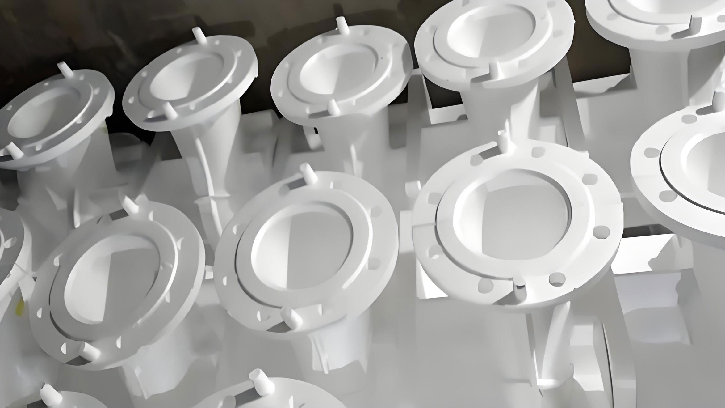
I mention full mold casting repeatedly because it illustrates an important contrast. In full mold casting, the pattern degradation can change the local pressure and temperature field, whereas in investment casting, the shell is already empty and the thermal field is governed mainly by shell thickness, preheat, and metal flow. That difference affects how confidently I can predict feeding. My simulation strategy therefore focused on solidification and feeding-path continuity rather than on foam decomposition. I still used the full mold casting comparison to justify why I did not change the process family. The thin wall, welding requirement, and dimensional tolerance made investment casting the stronger choice. In addition, full mold casting would not automatically solve the tough-material knock-off problem, because the gate-to-casting junction would still need a controlled fracture feature.
Initial gating architecture. The casting has relatively uniform wall thickness, so I selected a single transverse runner with inner gates. The transverse runner does not act as the main feeding reservoir in the sprue cup feeding capacity method. Instead, it is a feeding channel. The sprue cup is the main source of liquid metal, and the inner gates deliver that metal to the casting hot spots. The design calculation therefore proceeded from the hot spot to the inner gate, then to the transverse runner, and finally to the sprue cup.
The sprue cup feeding capacity method treats each casting hot spot as an equivalent cylindrical hot spot. The equivalent hot spot diameter is a practical way to relate a complex section to a cylindrical body with a comparable solidification modulus. For a rectangular hot spot section, the equivalent hot spot diameter can be read from a design chart. In my case, two locations, which I treated as hot spot A and hot spot B, had a section of approximately \(15 \ \text{mm} \times 75 \ \text{mm}\). The weight of the casting region fed by a single inner gate was approximately \(600 \ \text{g}\). Using the chart, I obtained an equivalent hot spot diameter of \(D_c = 23 \ \text{mm}\). The weight factor was obtained from the weight-factor chart, giving \(k = 0.93\). The inner gate equivalent hot spot diameter was then calculated as follows:
$$D_g = k D_c$$
$$D_g = 0.93 \times 23 = 21.39 \ \text{mm}$$
The ideal inner gate equivalent diameter would therefore be about \(21.39 \ \text{mm}\). However, the local casting geometry did not allow a circular gate of that diameter. The available space at the hot spot was limited, and a round gate would have interfered with the shell, the wax pattern, and the welding surface. I converted the gate to a rectangular section of approximately \(22 \ \text{mm} \times 20 \ \text{mm}\). This section was selected to approximate the required equivalent hot spot diameter while fitting the available space. The calculation is summarized in the following table.
| Parameter | Value | Basis |
|---|---|---|
| Hot spot section | \(15 \ \text{mm} \times 75 \ \text{mm}\) | Measured from casting geometry |
| Equivalent hot spot diameter, \(D_c\) | \(23 \ \text{mm}\) | Chart method for rectangular section |
| Weight of fed region | \(600 \ \text{g}\) | Approximate region assigned to one inner gate |
| Weight factor, \(k\) | \(0.93\) | Weight-factor chart |
| Theoretical inner gate diameter, \(D_g\) | \(21.39 \ \text{mm}\) | \(D_g = k D_c\) |
| Selected inner gate section | \(22 \ \text{mm} \times 20 \ \text{mm}\) | Geometry constraint and approximate equivalence |
Knock-off neck design. The most important change for production was not only the gate size but also the fracture control at the gate-to-casting interface. I designed a sharp-angle neck in the direction of the hammer impact. This neck creates stress concentration and limits the fracture zone. When the gate is struck, the stress concentrates at the neck, the material deforms locally, and the gate separates from the casting at a controlled location. I selected a neck angle of \(75^\circ\). The other direction did not require a neck because it had little influence on hammer separation, and adding another neck would increase mold complexity and the number of loose pieces. A small root allowance of approximately \(1.5 \ \text{mm}\) was left below the neck to reduce the risk of casting body undercut or missing material. The stress concentration can be expressed in a simplified way as:
$$\sigma_{\max} = K_t \frac{F}{A_n}$$
where \(\sigma_{\max}\) is the maximum local stress, \(K_t\) is the stress concentration factor, \(F\) is the applied force, and \(A_n\) is the neck cross-sectional area. The goal was not to make the neck as weak as possible. If the neck were too small, it could crack during wax injection, shell building, dewaxing, or pouring. The goal was to make the neck strong enough to survive mold making but weak enough under impact to separate cleanly. That balance is central to a successful hammer knock-off process. The impact energy available from the hammer can be approximated by:
$$E = \frac{1}{2} m v^2$$
where \(m\) is the hammer mass and \(v\) is the impact velocity. I did not rely on increasing hammer energy, because that would increase the risk of damage to the casting. Instead, I reduced the required separation energy by controlling the neck geometry and by ensuring that the gate itself could still feed the hot spot before solidification.
Transverse runner sizing. In the sprue cup feeding capacity method, the transverse runner does not provide the main feeding volume. It only needs to remain a reliable feeding channel. Therefore, the runner cross-section should be as small as possible while still satisfying the feeding condition. The runner equivalent hot spot diameter must be greater than the inner gate equivalent diameter by a practical factor. The design inequality is:
$$D_k \ge (1.15 \ \text{to} \ 1.25) D_g$$
Using the calculated inner gate diameter \(D_g = 21.39 \ \text{mm}\), the lower and upper bounds were:
$$D_{k,\min} = 1.15 \times 21.39 = 24.60 \ \text{mm}$$
$$D_{k,\max} = 1.25 \times 21.39 = 26.74 \ \text{mm}$$
Theoretically, a runner equivalent diameter between about \(24.6 \ \text{mm}\) and \(26.7 \ \text{mm}\) would be sufficient for feeding. In actual production, I selected a larger runner equivalent diameter of \(35 \ \text{mm}\). This decision was based on practical factors: the available rod-core size, the required welding surface between the runner and the inner gates, the need to reduce filling resistance, and the desire to keep the runner robust during shell building. A larger runner also reduces the risk of premature freezing when the pouring temperature fluctuates. The runner is not intended to be a large feeding reservoir, but it must not become a bottleneck. The selected runner equivalent diameter of \(35 \ \text{mm}\) provided a safe margin above the theoretical minimum.
| Runner parameter | Calculated or selected value | Comment |
|---|---|---|
| Inner gate equivalent diameter, \(D_g\) | \(21.39 \ \text{mm}\) | From hot spot calculation |
| Minimum runner diameter, \(1.15 D_g\) | \(24.60 \ \text{mm}\) | Theoretical lower bound |
| Maximum suggested runner diameter, \(1.25 D_g\) | \(26.74 \ \text{mm}\) | Theoretical upper bound |
| Selected runner equivalent diameter, \(D_k\) | \(35 \ \text{mm}\) | Practical choice for feeding, shell strength, and core availability |
| Runner function | Feeding channel | Not the primary feeding reservoir |
Sprue cup sizing. The sprue cup is the main feeding source in this gating system. It must contain enough liquid metal to compensate for solidification shrinkage and to maintain feeding pressure until the casting hot spots are isolated. At the same time, the sprue cup should not be unnecessarily large, because excess metal reduces process yield and increases knock-off weight. I used the standard dimension table for a single transverse runner with a square cross-section. With \(D_k = 35 \ \text{mm}\), I selected the corresponding group. Because the inner gate spacing imposed a minimum length, the shortest practical length was \(105 \ \text{mm}\), and the selected sprue cup diameter was \(70 \ \text{mm}\). The relevant standard dimensions are shown in the following table.
| \(D_k\) / mm | \(D_1\) / mm | \(D_2\) / mm | \(K\) / mm | \(H\) / mm | \(L\) options / mm | \(D\) options / mm |
|---|---|---|---|---|---|---|
| 25 | 25 | 20 | 25 | 25 | \(2D_k, 3D_k, 4D_k\) | 50, 60, 70, 80 |
| 30 | 30 | 25 | 30 | 30 | \(2D_k, 3D_k, 4D_k\) | 60, 70, 80, 90 |
| 35 | 35 | 30 | 35 | 35 | \(2D_k, 3D_k, 4D_k\) | 70, 80, 90, 100 |
| 40 | 40 | 35 | 40 | 40 | \(2D_k, 2.5D_k, 3D_k\) | 80, 90, 100, 110 |
| 45 | 45 | 40 | 45 | 45 | \(2D_k, 3D_k\) | 90, 100, 110, 120 |
| 50 | 50 | 45 | 50 | 50 | \(2D_k, 2.5D_k, 3D_k\) | 100, 110, 120, 130 |
With \(D_k = 35 \ \text{mm}\), I used \(D_1 = 35 \ \text{mm}\), \(D_2 = 30 \ \text{mm}\), \(K = 35 \ \text{mm}\), and \(H = 35 \ \text{mm}\). The length \(L\) was taken as \(105 \ \text{mm}\), and the sprue cup diameter \(D\) was taken as \(70 \ \text{mm}\). These choices kept the sprue cup compact while still providing sufficient feeding volume. The complete module was then assembled with the transverse runner and inner gates. The goal was to create a stable tree that could survive shell building and provide a continuous feed path.
Initial solidification simulation. I used a casting CAE environment with preprocessing, solver, and postprocessing modules. The preprocessing step involved meshing the three-dimensional model. The solver calculated the thermal field and solidification progression. The postprocessing step displayed liquid fraction, temperature gradients, isolated liquid regions, and shrinkage porosity tendency. In this project, I focused on solidification rather than filling because the gating dimensions were already based on feeding calculations, and the main risk was shrinkage at the hot spots. The initial simulation showed that the overall casting had a low shrinkage tendency in most regions, but the inner gate location exhibited very small shrinkage indications. More importantly, the solidification sequence showed that the inner gate froze before the casting hot spot. A clear flow blockage or断流 condition appeared at the gate. That meant the hot spot could not receive enough liquid feeding after the gate solidified. Based on previous production experience, I predicted that the real casting would show a certain probability of shrinkage porosity at the hot spot, which could affect later machining holes. The initial simulation findings are summarized below.
| Observation | Initial simulation result | Interpretation |
|---|---|---|
| Overall shrinkage tendency | Relatively low in most of the casting | Uniform wall thickness helps |
| Inner gate solidification | Gate froze before hot spot | Feeding path blocked |
| Hot spot feeding | Insufficient liquid feeding | Risk of shrinkage porosity |
| Isolated liquid region | Small shrinkage indication at gate location | Not acceptable for machining holes |
| Required action | Increase feeding channel capability | Optimize gate volume, weld face, and cooling |
The physical reason for the blockage can be explained by the solidification modulus. The modulus of a section is the ratio of its volume to its cooling surface area:
$$M = \frac{V}{A}$$
where \(M\) is the modulus, \(V\) is the volume, and \(A\) is the effective cooling surface area. According to Chvorinov’s rule, solidification time depends on the modulus:
$$t_s = B M^n$$
where \(t_s\) is solidification time, \(B\) is a mold constant, and \(n\) is an exponent typically close to 2 for many castings. If the inner gate has a smaller modulus than the casting hot spot, the gate solidifies earlier and stops feeding. The initial inner gate had a small neck section and a relatively high cooling surface area, so it lost heat quickly. The weld face area was also limited. As a result, the gate modulus was too low relative to the hot spot. The feeding condition can be written as:
$$M_g > M_c$$
where \(M_g\) is the modulus of the gate and \(M_c\) is the modulus of the casting hot spot. In the initial design, this condition was not satisfied during the critical feeding period. The simulation showed that the gate did not remain open long enough. This was the key problem to solve.
Optimization of the inner gate. The initial simulation made it clear that the gate needed a stronger feeding capability without making the knock-off neck so large that hammer separation became impossible. I considered several variables: neck cross-section, gate volume, gate height, weld face area, and the thermal contact between the gate and the casting. The most effective changes were increasing the gate volume and increasing the weld face area. I also reduced the heat loss by changing the gate shape. The initial weld face area was approximately \(1,950 \ \text{mm}^2\). I increased it to approximately \(2,850 \ \text{mm}^2\). This larger weld face reduced the thermal resistance between the runner, gate, and casting hot spot. The thermal resistance of the feeding path can be approximated as:
$$R_{\text{th}} = \frac{L}{k A_w}$$
where \(R_{\text{th}}\) is thermal resistance, \(L\) is the path length, \(k\) is thermal conductivity, and \(A_w\) is the weld face or contact area. Increasing \(A_w\) lowers \(R_{\text{th}}\), which helps maintain a liquid feeding path. Increasing the gate volume also increases the heat content of the gate, so the gate remains liquid longer. The gate modulus can be written as:
$$M_g = \frac{V_g}{A_{g,\text{cool}}}$$
If the gate volume \(V_g\) increases and the cooling surface area \(A_{g,\text{cool}}\) does not increase proportionally, the gate modulus increases. The gate then solidifies later and feeds the hot spot for a longer time. The design challenge was to increase the gate modulus while keeping the neck small enough to fracture under impact.
I also reduced the effective gate height by using an angled weld face. The original gate height was about \(15 \ \text{mm}\). Directly reducing the height would have caused problems with sand filling around the gate and shell support, so I introduced an angled welding surface instead. This design reduced the bottom gap of the module and allowed the shell to fill the space during shell building. A stronger shell around the gate reduced the risk of shell cracking and improved dimensional stability. The module was placed horizontally during knock-off, and the sprue cup was angled relative to the horizontal plane. This made hammering easier and more ergonomic. The angled weld face also helped distribute the load during shell building and pouring. The optimization variables are summarized in the following table.
| Variable | Initial design | Optimized design | Reason for change |
|---|---|---|---|
| Inner gate weld face area | \(1,950 \ \text{mm}^2\) | \(2,850 \ \text{mm}^2\) | Lower thermal resistance and stronger feeding path |
| Inner gate volume | Limited by original height and shape | Increased through angled weld face and larger section | Delay gate solidification and improve feeding |
| Inner gate height | Approximately \(15 \ \text{mm}\) | Effectively reduced with an angled face | Reduce heat loss without harming shell filling |
| Neck angle | \(75^\circ\) | \(75^\circ\) retained | Stress concentration for hammer knock-off |
| Root allowance below neck | \(1.5 \ \text{mm}\) | \(1.5 \ \text{mm}\) retained | Prevent casting undercut and missing material |
| Module bottom gap | Larger | Smaller, filled by shell | Increase shell strength and support |
Transverse runner optimization. The initial simulation also showed that the sprue cup contained enough liquid metal to meet the feeding demand. The transverse runner feeding path was smooth, and there was excess liquid metal between the two inner gates. I therefore removed the middle portion of the transverse runner. This reduced runner weight and improved process yield. At the same time, the weld face between the runner and the inner gates had to increase because the inner gate weld face had increased. The runner thickness was kept unchanged, but the contact area was enlarged. I also added a thread-like structure at the sprue cup and its connection to the runner. This structure increased the strength of the rod module and the shell. The sprue cup and runner were connected by a web, which improved the overall rigidity of the module during handling and shell building. The changes are listed below.
| Runner or module feature | Initial condition | Optimized condition | Expected effect |
|---|---|---|---|
| Middle section of transverse runner | Continuous runner between gates | Removed where liquid metal was excessive | Reduce weight and improve yield |
| Runner-to-gate weld face | Original contact area | Increased while maintaining thickness | Match larger inner gate and maintain feeding |
| Sprue cup connection | Simple connection | Thread structure and web connection | Increase module and shell strength |
| Module orientation | Original handling position | Horizontal knock-off with angled sprue cup | Easier and more consistent hammering |
| Shell support around gate | Larger bottom gap | Smaller gap filled by shell | Better support and lower shell cracking risk |
Optimized solidification simulation. After optimizing the inner gate and runner, I reran the solidification simulation. The new results showed that the gate no longer exhibited the断流 condition before the hot spot solidified. The feeding path remained open through the critical period. The shrinkage tendency at the hot spot was eliminated in the simulation. The optimized parameters are summarized in the following table. The simulation confirmed that increasing the weld face area to about \(2,850 \ \text{mm}^2\) was sufficient to maintain feeding when combined with the larger gate volume and reduced heat loss. The runner optimization also reduced excess metal without creating a feeding blockage.
| Simulation result | Initial design | Optimized design |
|---|---|---|
| Gate solidification before hot spot | Yes, clear blockage | No |
| Feeding path continuity | Broken before hot spot isolation | Continuous during critical period |
| Hot spot shrinkage tendency | Small shrinkage indication | Eliminated in simulation |
| Runner excess metal | Excess between gates | Reduced by removing middle section |
| Module strength | Adequate but not optimized | Improved by thread and web structure |
| Knock-off feature | Neck present but gate feeding insufficient | Neck retained and feeding improved |
The optimized gating system therefore combined two seemingly opposite requirements. The feeding path had to be strong enough to keep the hot spot liquid, but the knock-off neck had to be weak enough to fracture under a hammer blow. I achieved this by separating the functions. The large weld face and gate volume provided feeding. The small, sharp neck provided fracture control. The root allowance protected the casting body. The angled weld face reduced heat loss and improved shell support. The runner was reduced where it was not needed, and the sprue cup remained the main feeding reservoir. This functional separation is one of the most important lessons from the project. A single gate feature cannot simultaneously maximize feeding and minimize knock-off force unless the geometry is carefully divided into a feeding zone and a fracture zone.
Thermal and fluid considerations. Although I did not perform a full filling simulation in the final iteration, I considered the main fluid flow and heat transfer factors. The continuity equation for the liquid metal is:
$$Q = A v$$
where \(Q\) is volumetric flow rate, \(A\) is cross-sectional area, and \(v\) is flow velocity. A larger runner and gate reduce velocity for a given flow rate, which lowers turbulence and reduces the risk of gas entrapment. However, a larger gate also increases the knock-off weight and may increase the required separation energy. The balance is therefore critical. The pressure loss along the feeding channel can be approximated by a Hagen-Poiseuille-like relation:
$$\Delta P = \frac{8 \mu L Q}{\pi r^4}$$
where \(\Delta P\) is pressure loss, \(\mu\) is dynamic viscosity, \(L\) is channel length, \(Q\) is flow rate, and \(r\) is channel radius. This relation shows why a small neck can create a large pressure drop. Even if the runner and sprue cup are large, a constricted neck can limit feeding. That is exactly what happened in the initial design. The neck was necessary for knock-off, but it also became a feeding bottleneck. Increasing the weld face and gate volume effectively reduced the bottleneck without eliminating the neck. The thermal field during solidification can be described by the heat conduction equation:
$$\frac{\partial T}{\partial t} = \alpha \nabla^2 T$$
where \(T\) is temperature, \(t\) is time, and \(\alpha\) is thermal diffusivity. The gate cools faster when it has a large surface area and a small volume. By increasing the gate volume and the weld face area, I changed the local \(V/A\) ratio and the thermal resistance between the gate and the casting. The simulation solved this equation numerically with boundary conditions representing the shell, air, and metal. The result was a delayed gate solidification and a longer feeding window. The Niyama criterion can be used as an indicator of shrinkage porosity:
$$\frac{G}{\sqrt{R}} > C_{\text{Niyama}}$$
where \(G\) is temperature gradient, \(R\) is cooling rate, and \(C_{\text{Niyama}}\) is a critical value. Regions below the critical value are more likely to contain shrinkage porosity. In the initial design, the hot spot near the gate fell below the criterion. In the optimized design, the feeding path remained open, and the hot spot did not show the same deficiency. I used these concepts to interpret the simulation rather than relying only on visual shrinkage plots.
Trial production and validation. The first trial batch contained 100 pieces. The wax patterns were injected with the optimized gate geometry. During shell building, no pieces fell off the tree. This was important because the larger gate and angled weld face were designed to improve shell support, and the trial confirmed that the module was robust enough for production handling. After pouring, the castings were knocked off by hammering the sprue rod. The gate separated easily at the neck. The fracture surface was flat and clean, with no obvious sharp protrusions. The casting body did not show missing material at the gate location. The trial results are summarized below.
| Validation item | Result | Interpretation |
|---|---|---|
| Trial batch size | 100 pieces | Representative first production trial |
| Wax pattern and shell building | No dropped pieces | Module and shell strength sufficient |
| Hammer knock-off | Easy separation at neck | Fracture control successful |
| Fracture surface | Flat and clean, no major sharp corners | Controlled stress concentration |
| X-ray inspection | No internal defects at hot spot; slight shrinkage at local corners | Matches simulation prediction |
| Machined pieces | 95 pieces | High-precision holes free of shrinkage porosity |
The X-ray inspection showed no internal defects at the hot spot. Slight shrinkage was observed at local corners, which matched the simulation result. Those corner regions were not critical for the machined holes or the welded joint. After machining, 95 pieces were inspected, and the high-precision holes showed no shrinkage porosity. This confirmed that the optimized feeding design was effective. The trial also demonstrated that the hammer knock-off process was stable. The elimination of flame cutting reduced labor, gas consumption, and cut-off allowance. The production floor could remove the gating system quickly and with less risk of thermal damage to the casting. The clean fracture surface also reduced the need for grinding and finishing.
Production performance improvement. I compared the new process with similar castings produced by the previous route. The new process achieved a significant increase in knock-off and cleaning productivity, as well as a higher process yield. The comparison is shown in the following table. The productivity of knock-off and cleaning increased from 260 pieces per shift to 600 pieces per shift, an improvement of about 130.77%. The process yield increased from 55% to 68%, an improvement of about 23.64%. These gains came from the combined effects of the optimized gating design, the reduced runner weight, the stable shell, and the clean hammer knock-off.
| Performance measure | Similar casting with previous route | This optimized forklift head | Improvement |
|---|---|---|---|
| Knock-off and cleaning productivity | 260 pieces per shift | 600 pieces per shift | 130.77% |
| Process yield | 55% | 68% | 23.64% |
| Gate removal method | Flame cutting | Hammer knock-off | Cost reduction and efficiency gain |
| Risk of handling damage | Higher due to repeated hammering or flame cutting | Lower due to controlled neck fracture | Improved quality |
| Shell-related scrap | Higher risk in thin-wall modules | Reduced by stronger module and shell design | Improved stability |
The cost reduction was not limited to labor. Flame cutting required fuel gas, cutting tips, and operator skill. It also created a heat-affected zone near the gate and sometimes required additional grinding. The hammer knock-off process required only a controlled blow at the neck. Because the fracture location was designed, the casting body was protected. The process yield improvement also reduced melting energy and scrap recycling. The optimized runner removed excess metal between the gates, which lowered the amount of metal that had to be melted and then returned to the furnace. The improved shell support reduced the risk of shell cracking and casting deformation. All of these factors contributed to a lower total production cost.
Why full mold casting remained a reference, not the selected route. Throughout the project, I continued to use full mold casting as a reference point because it is a well-known process for complex castings. In full mold casting, the foam pattern decomposes during pouring, and the decomposition products must escape through the coating and sand. If venting is insufficient, gas defects, incomplete filling, or carbon pickup can occur. For a low-carbon steel forklift head with a thin wall and a welded assembly requirement, those risks are difficult to accept. Investment casting provided a cleaner cavity, better surface finish, and more predictable shell strength. However, the full mold casting perspective helped me focus on feeding-path continuity. In full mold casting, the gate must often be designed to compensate for the thermal effects of foam decomposition. In investment casting, the thermal effects are different, but the need for an open feeding path is the same. I therefore treated the full mold casting comparison as a design check: if the feeding path would be marginal in full mold casting, it would also be marginal in investment casting unless the gate modulus and weld face area were increased. That insight supported the decision to enlarge the inner gate weld face and volume.
Another reason I did not select full mold casting was the knock-off requirement. Full mold casting can produce complex shapes, but the gate-to-casting junction still needs a fracture feature. The tough low-carbon steel would still resist hammer separation if the neck were not properly designed. In addition, the foam pattern and coating process would add variables that could affect the neck dimensions and surface quality. Investment casting allowed me to produce the neck with high dimensional precision. The wax pattern could be inspected, the shell could be built around the neck, and the neck geometry could be repeated reliably. That repeatability is essential for a stable hammer knock-off operation. The full mold casting option therefore remained a useful comparison, but it was not the best route for this specific component.
Design rules derived from the project. I summarized the most important design rules for future low-carbon steel investment castings with hammer knock-off requirements. These rules are not limited to forklift heads. They can be applied to other thin-wall, hollow, welded components with tough material specifications. The rules are shown in the following table.
| Design rule | Practical expression | Reason |
|---|---|---|
| Calculate the hot spot first | Determine \(D_c\) and then \(D_g = k D_c\) | Establishes the required feeding size |
| Do not let the neck control feeding | Separate the feeding zone from the fracture zone | A small neck can block liquid feeding |
| Increase weld face area when gate volume is limited | Raise \(A_w\) to reduce \(R_{\text{th}}\) | Improves heat transfer and feeding path continuity |
| Use an angled weld face if height reduction is difficult | Keep shell fillability while reducing heat loss | Maintains shell strength and reduces gate cooling |
| Keep the runner as small as practical but not restrictive | Use \(D_k \ge (1.15 \ \text{to} \ 1.25)D_g\) with production margin | Prevents premature freezing and reduces weight |
| Remove excess runner metal | Delete non-feeding sections between gates | Improves yield without harming feeding |
| Design stress concentration for knock-off | Use a sharp neck angle and a small root allowance | Controls fracture location and protects the casting |
| Validate with solidification simulation | Check gate modulus, feeding path, and shrinkage tendency | Reduces trial-and-error and improves reliability |
| Compare with full mold casting principles | Use full mold casting experience as a feeding-path check | Broadens process understanding and avoids blind spots |
The formula \(D_g = k D_c\) was the starting point. The inequality \(D_k \ge (1.15 \ \text{to} \ 1.25)D_g\) was the runner check. Chvorinov’s rule, \(t_s = B M^n\), explained why the initial gate froze too early. The modulus definition, \(M = V/A\), explained why increasing gate volume and weld face area delayed gate solidification. The thermal resistance relation, \(R_{\text{th}} = L/(k A_w)\), explained why the larger weld face improved feeding. The stress concentration relation, \(\sigma_{\max} = K_t F/A_n\), explained why the neck could still fracture under a controlled hammer blow. These equations formed a practical framework for the optimization.
Additional simulation interpretation. I want to emphasize that simulation did not replace the feeding calculation. Instead, it showed where the calculation needed a practical correction. The theoretical inner gate diameter was about \(21.39 \ \text{mm}\), but the actual gate was rectangular and had a neck. The theoretical runner diameter was between \(24.6 \ \text{mm}\) and \(26.7 \ \text{mm}\), but the selected runner was \(35 \ \text{mm}\) for production robustness. These differences are normal in investment casting. The simulation helped me see that the neck, not the runner, was the limiting feature. Once I understood that, I changed the gate volume and weld face rather than simply enlarging the runner. This is a key point. A larger runner alone would not have solved the problem if the neck remained a bottleneck. The feeding path must be evaluated as a series of thermal resistances and moduli. Each segment must remain open until the previous segment has finished feeding. The critical path is the segment with the smallest modulus or the highest thermal resistance. In the initial design, that segment was the inner gate neck. In the optimized design, the neck was still small enough for knock-off, but the surrounding gate volume and weld face were large enough to keep the feeding path open.
The solidification sequence can be expressed as a chain of conditions:
$$t_{s,\text{sprue}} > t_{s,\text{runner}} > t_{s,\text{gate}} > t_{s,\text{hot spot}}$$
This inequality is a simplified way to ensure directional solidification from the casting toward the sprue. In the initial design, the chain was broken because \(t_{s,\text{gate}}\) was less than \(t_{s,\text{hot spot}}\). In the optimized design, the chain was restored. The sprue cup remained liquid longest because it had the largest volume and was designed as the main feeding reservoir. The runner remained open longer than the gate. The gate remained open longer than the hot spot. The hot spot therefore received liquid metal until it was isolated by solidification. This sequence is the foundation of a sound casting. The simulation confirmed that the optimized design approached this sequence. The trial castings confirmed that the simulation was reliable.
Quality and inspection considerations. The X-ray inspection was an important part of validation because internal shrinkage is not always visible on the surface. The hot spot region was inspected carefully because it was the highest-risk area. No internal defects were found at the hot spot. Slight shrinkage at local corners was acceptable because those corners were not load-bearing and did not intersect the high-precision holes. After machining, 95 pieces were checked, and the holes were free of shrinkage porosity. This result was consistent with the simulation. The clean fracture surface at the neck also indicated that the stress concentration was working as intended. If the fracture surface had shown a large protrusion or a jagged edge, it would have indicated that the neck angle, root allowance, or gate modulus was not optimized. The trial results showed that the design was robust. The process was released to production with the optimized gating system. The production team could knock off the castings easily, and the cleaning operation became faster and safer. The flame-cutting station was no longer required for this component, which reduced operating cost and improved working conditions.
Final perspective. From my perspective, the most valuable outcome of this project was not a single dimension change. It was the demonstration that a tough, low-carbon steel casting can be designed for hammer knock-off without sacrificing internal soundness. The key was to treat the gating system as a thermal and mechanical system. Thermally, the gate must remain open long enough to feed the hot spot. Mechanically, the neck must concentrate stress so that the gate separates under impact. These two requirements pull in opposite directions. The solution was to separate them functionally. The weld face and gate volume provided feeding. The sharp neck and root allowance provided fracture control. The runner was reduced where it was not needed. The sprue cup remained the main feeding reservoir. The simulation guided the optimization, and the trial production validated it. The production data showed a large increase in productivity and process yield. The flame-cutting operation was eliminated. The casting quality was maintained. The full mold casting comparison remained useful throughout because it reminded me that feeding-path continuity is a universal principle, even when the mold material and pattern system are different. In future projects, I will continue to use full mold casting as a reference when evaluating gating concepts, but I will select the process route based on the specific requirements of the component. For this thin-wall, hollow, welded forklift head, investment casting with an optimized hammer knock-off gating system proved to be the best solution.
Summary of optimized parameters. The final optimized parameters are collected in the following table for clarity. These values represent the production design that was validated by simulation and trial production.
| Parameter | Final optimized value |
|---|---|
| Hot spot section | Approximately \(15 \ \text{mm} \times 75 \ \text{mm}\) |
| Equivalent hot spot diameter, \(D_c\) | \(23 \ \text{mm}\) |
| Weight factor, \(k\) | \(0.93\) |
| Theoretical inner gate diameter, \(D_g\) | \(21.39 \ \text{mm}\) |
| Selected inner gate section | \(22 \ \text{mm} \times 20 \ \text{mm}\) |
| Neck angle | \(75^\circ\) |
| Root allowance below neck | \(1.5 \ \text{mm}\) |
| Initial weld face area | \(1,950 \ \text{mm}^2\) |
| Optimized weld face area | \(2,850 \ \text{mm}^2\) |
| Initial gate height | Approximately \(15 \ \text{mm}\) |
| Optimized gate height approach | Angled weld face with reduced effective height |
| Transverse runner equivalent diameter, \(D_k\) | \(35 \ \text{mm}\) |
| Sprue cup diameter, \(D\) | \(70 \ \text{mm}\) |
| Sprue cup length, \(L\) | \(105 \ \text{mm}\) |
| Runner optimization | Middle section removed, weld face increased |
| Module strengthening | Thread structure and web connection |
| Knock-off method | Hammer blow at designed neck |
| Validation batch | 100 pieces |
| Machined and inspected | 95 pieces |
| Hot spot X-ray result | No internal defects |
| Machined hole result | No shrinkage porosity |
The equations that supported the design can also be collected:
$$D_g = k D_c$$
$$D_k \ge (1.15 \ \text{to} \ 1.25) D_g$$
$$M = \frac{V}{A}$$
$$t_s = B M^n$$
$$R_{\text{th}} = \frac{L}{k A_w}$$
$$\sigma_{\max} = K_t \frac{F}{A_n}$$
$$E = \frac{1}{2} m v^2$$
$$Q = A v$$
$$\Delta P = \frac{8 \mu L Q}{\pi r^4}$$
$$\frac{\partial T}{\partial t} = \alpha \nabla^2 T$$
$$\frac{G}{\sqrt{R}} > C_{\text{Niyama}}$$
These relationships formed the technical basis for the optimization. The full mold casting comparison provided a broader process perspective, while the investment casting simulation and trial production provided the specific validation. The final process achieved clean hammer knock-off, sound internal quality, higher productivity, and better process yield. I consider this a successful example of using feeding theory, CAE simulation, and fracture control together to solve a difficult production problem in low-carbon steel investment casting.