
In industrial applications demanding exceptional wear resistance, such as flour milling, the longevity and performance of critical components directly impact productivity and operational cost. Milling rollers, which undergo continuous high-speed abrasive wear, are traditionally manufactured from white cast iron due to its inherent hardness derived from a microstructure rich in hard carbides embedded in a pearlitic matrix. However, the severe service conditions often lead to premature failure of these rollers. Therefore, enhancing the surface properties of white cast iron components through advanced surface engineering techniques is of paramount practical and economic importance.
Plasma Arc Remelting (PAR) presents a highly effective method for surface modification. This process utilizes a constricted, high-energy-density plasma arc to rapidly melt a thin surface layer of the substrate material. Subsequent rapid quenching by the cold bulk material results in significant microstructural refinement and homogenization. For white cast iron, this can lead to the dissolution of primary carbides and the formation of finer, harder phases, thereby substantially improving surface hardness and wear resistance without compromising the toughness of the core material. This study systematically investigates the PAR process applied to the teeth of a white cast iron milling roller. Through designed experimentation and analysis, we identify the optimal process parameters and elucidate the underlying metallurgical transformations.
Materials and Experimental Methodology
The substrate material used in this investigation was a low-alloyed white cast iron, specifically designed for milling roller applications. Its chemical composition, determined via optical emission spectrometry, is presented in Table 1. The key feature is its hypereutectic carbon content, which ensures the formation of a substantial volume fraction of hard carbides.
| C | Si | Mn | Cr | Ni | Cu | Ti | B | S | P |
|---|---|---|---|---|---|---|---|---|---|
| 3.86-3.87 | 0.25-0.30 | 0.56-0.58 | 0.95-0.97 | 0.30 | 0.034-0.036 | 0.030-0.031 | 0.001 | 0.048-0.050 | 0.450-0.470 |
Cylindrical roller specimens (Ø220 mm × 300 mm) were fabricated via centrifugal casting to replicate the industrial manufacturing process. Individual teeth sections were then extracted using wire-electrical discharge machining (EDM) to preserve the integrity of the microstructure at the region of interest. The PAR treatment was conducted using a customized, numerically controlled setup based on a high-hardness roller processing machine. A non-transferred arc plasma torch with a 1.6 mm diameter tungsten electrode was employed. The primary adjustable process parameters identified for this study were:
- Working Arc Current (I, in Amperes)
- Torch-to-Surface Standoff Distance (d, in millimeters)
- Traverse Speed of the Torch (v, in mm/s)
- Plasma Forming Gas Pressure (P, in MPa)
The shielding and plasma-forming gas was argon. Post-treatment, cross-sections of the remelted teeth were prepared through standard metallographic techniques, etched with a 4% Nital solution, and examined using optical microscopy. Microhardness profiles from the remelted surface down to the unaffected base material were obtained using a Vickers hardness tester with a 500 gf load, which were later correlated to Rockwell C scale values. Surface hardness was measured directly on the tooth crest using a Rockwell hardness tester.
Experimental Design and Analysis via Orthogonal Array
To efficiently investigate the influence of the four key parameters (I, d, v, P) with three levels each, an L9(3^4) orthogonal array was adopted. This design reduces the required number of experiments from 81 (full factorial) to just 9, while still allowing for a statistically meaningful analysis of the main effects. The chosen factor levels and the experimental layout with the measured responses—surface hardness (HRC) and remelted layer depth (mm)—are detailed in Table 2.
| Expt. No. | Traverse Speed, v (mm/s) | Arc Current, I (A) | Standoff Distance, d (mm) | Gas Pressure, P (MPa) | Surface Hardness (HRC) | Remelt Depth (mm) |
|---|---|---|---|---|---|---|
| 1 | 1.5 | 4.5 | 5 | 6 | 65.0 | 1.080 |
| 2 | 1.5 | 5.0 | 6 | 7 | 64.0 | 0.993 |
| 3 | 1.5 | 7.0 | 7 | 6.5 | 64.8 | 0.837 |
| 4 | 2.0 | 4.5 | 6 | 6.5 | 66.5 | 1.103 |
| 5 | 2.0 | 5.0 | 7 | 6 | 63.2 | 0.972 |
| 6 | 2.0 | 7.0 | 5 | 7 | 66.1 | 1.061 |
| 7 | 2.5 | 4.5 | 7 | 7 | 65.0 | 1.044 |
| 8 | 2.5 | 5.0 | 5 | 6.5 | 65.0 | 1.132 |
| 9 | 2.5 | 7.0 | 6 | 6 | 67.2 | 0.996 |
The results were analyzed using analysis of means. For each factor, the average response (e.g., hardness) at each level was calculated. The range (R) for each factor, defined as the difference between the maximum and minimum average response, indicates the factor’s influence magnitude. A larger R signifies a greater effect on the response variable. The calculated mean responses and ranges for both hardness and remelt depth are summarized in Table 3.
| Factor | Mean Surface Hardness (HRC) by Level | Range (R_H) | Mean Remelt Depth (mm) by Level | Range (R_D) | ||||
|---|---|---|---|---|---|---|---|---|
| Level 1 | Level 2 | Level 3 | Level 1 | Level 2 | Level 3 | |||
| Arc Current (I) | 65.50 | 64.07 | 66.03 | 1.96 | 1.076 | 1.032 | 0.965 | 0.111 |
| Standoff Distance (d) | 65.37 | 65.90 | 64.33 | 1.57 | 1.091 | 1.031 | 0.951 | 0.140 |
| Gas Pressure (P) | 65.13 | 65.03 | 65.43 | 0.40 | 1.016 | 1.033 | 1.024 | 0.017 |
| Traverse Speed (v) | 64.60 | 65.27 | 65.73 | 1.13 | 0.970 | 1.045 | 1.057 | 0.087 |
Analysis of Table 3 leads to clear conclusions regarding parameter significance. For achieving maximum surface hardness, the working arc current (I) is the most influential parameter (R_H = 1.96), followed by the standoff distance (d). In contrast, for maximizing the depth of the remelted and hardened layer, the standoff distance (d) is the dominant factor (R_D = 0.140), with arc current also playing a role. Both gas pressure (P) and traverse speed (v) exhibit relatively minor influence on the responses within the tested ranges. The optimal level for each factor can be identified from the level means: for hardness, Level 3 for Current (~7.0 A), Level 2 for Standoff (~6 mm), Level 3 for Speed (~2.5 mm/s), and Level 3 for Pressure (~7 MPa). For depth, the optimal levels are Level 1 for Current (~4.5 A), Level 1 for Standoff (~5 mm), Level 3 for Speed, and Level 2 for Pressure (~6.5 MPa). Since a balance between high hardness and sufficient case depth is desired, a compromise must be struck, prioritizing the factors with the strongest effects.
Parametric Influence and Mechanism Analysis
Effect of Working Arc Current
Arc current is the primary energy input parameter in PAR. Its effect on surface hardness and remelt depth, with other parameters held constant (d=6 mm, v=2.5 mm/s, P=6.5 MPa), is graphically represented in Figure 1. The relationship can be modeled by a power-law dependence, where the energy density (E) delivered to the surface is proportional to the current:
$$ E \propto \frac{I \cdot V}{v} $$
where V is the arc voltage (relatively stable for a given gas and standoff). As current increases from a threshold of about 4.0 A, both hardness and depth increase monotonically. Below this threshold, insufficient energy is delivered to cause significant melting, resulting only in a heat-affected zone. The increase in hardness is attributed to more complete dissolution of the original coarse carbides and a finer, more uniform redistribution of carbides upon solidification. The increased depth is a direct consequence of greater heat penetration. However, beyond approximately 7.0 A, the risk of excessive melting and geometric distortion (“collapsing” of the tooth tip) becomes significant, rendering the part unusable. Therefore, the current must be optimized below this critical point.
Effect of Torch Standoff Distance
The standoff distance governs the degree of arc constriction and plasma jet divergence before it impinges on the white cast iron surface. As shown in Figure 2, with fixed parameters (I=7.0 A, v=2.5 mm/s, P=6.5 MPa), both hardness and remelt depth decrease as distance increases. This is primarily due to the radial expansion of the plasma jet, which reduces its power density according to an inverse-square relationship approximation:
$$ q(d) \approx \frac{Q_0}{4 \pi d^2} $$
where \( q(d) \) is the heat flux at the surface and \( Q_0 \) is related to the power at the torch nozzle. At distances greater than 7-8 mm, the energy density becomes too low to cause melting, and the process effectively acts as a conventional hardening heat treatment, resulting in a sharp drop in hardness. The optimal range for achieving a well-defined, high-quality remelted pool was found to be between 5 and 7 mm.
Effect of Torch Traverse Speed and Gas Pressure
Traverse speed controls the interaction time between the heat source and a given point on the white cast iron surface. Higher speeds reduce the specific energy input (\(E \propto 1/v\)), leading to shallower remelting and less time for homogenization, which can slightly reduce peak hardness, as seen in Figure 3. However, within the practical range of 1.5 to 2.5 mm/s, its effect is less pronounced compared to current and distance. This parameter is often adjusted last to fine-tune productivity and heat input.
Gas pressure, within the stable operating window of the plasma torch, showed the least significant effect on the responses (Table 3). Its primary role is to maintain arc stability and shape. While it influences arc voltage and stiffness, its variation over a reasonable range (6.0-7.0 MPa) did not cause statistically significant changes in the measured hardness or depth for this white cast iron alloy.
Based on the orthogonal analysis and the study of individual effects, a balanced set of optimal parameters for hardening the white cast iron roller teeth was determined: I = 7.0 A, d = 5.5 mm, v = 2.0 mm/s, P = 6.5 MPa. This combination aims to deliver high surface hardness (>65 HRC) while maintaining a controlled remelt depth of approximately 1.0 mm to prevent tooth weakening.
Microstructural Evolution in the Remelted Zone
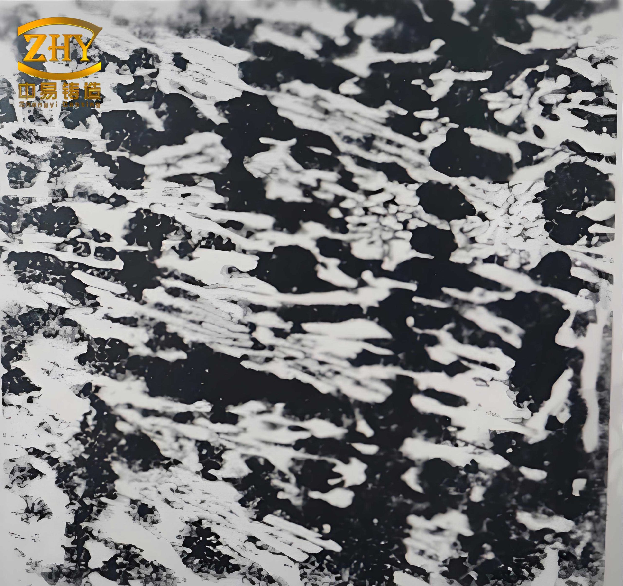
The primary objective of remelting white cast iron is to modify its near-surface microstructure. In its as-cast state, the hypereutectic white cast iron exhibits a microstructure comprising primary, coarse, script-like M₃C carbides (where M is primarily Fe with some Cr) in a matrix of transformed ledeburite (eutectic mixture of austenite, now pearlite, and carbide) and pearlite.
The PAR process subjects a thin layer to extreme heating, melting it completely, followed by ultra-rapid solidification. This drastic thermal cycle results in a significant microstructural transformation. The remelted zone consistently shows a transition from the original hypereutectic structure to a refined mixture of eutectic and hypereutectic structures. The key changes are:
- Carbide Refinement and Redistribution: The coarse primary carbides are entirely dissolved in the molten pool. Upon solidification, carbides re-precipitate in a much finer, more interconnected network. The high cooling rate suppresses the growth of large primary carbides, leading to a refined eutectic carbide structure.
- Matrix Transformation: The matrix in the remelted zone is predominantly a very fine ledeburitic structure, with the metallic constituent transforming to a harder phase mixture (e.g., very fine pearlite or even martensite, depending on alloying and cooling rate) rather than the coarser pearlite found in the base white cast iron.
- Directional Solidification: A clear epitaxial growth pattern is observed, where the newly formed carbide network grows preferentially perpendicular to the tooth’s sidewalls. This directionality aligns with the maximum heat extraction direction, which is radially inward from the surface toward the cooler bulk material. The growth morphology can be related to the thermal gradient (G) and solidification rate (R). The product G*R, which influences microstructure scale, is extremely high in PAR, leading to the observed fine microstructural features.
The microhardness profile across the treated zone confirms this microstructural gradient. Hardness peaks at the surface (corresponding to the finest as-solidified structure) and gradually decreases through the remelted zone, the heat-affected zone (where solid-state transformations occur), and finally to the base material hardness. The depth where hardness matches the base material defines the effective hardening depth.
Performance Implications and Concluding Synthesis
The successful application of PAR to white cast iron milling rollers yields tangible performance benefits. The surface hardness is elevated from approximately 58 HRC in the as-cast state to a range of 65-67 HRC. This ~15% increase in hardness directly translates to enhanced abrasive wear resistance. Furthermore, the controlled, shallow depth of the remelted layer (≈1.0 mm) ensures that the toughening effect of the underlying ductile iron core is preserved, providing good resistance to impact and fatigue.
An interesting and beneficial side effect observed in practice is the “blunting” or rounding of the sharp tooth crests after remelting. While this reduces geometric sharpness, it proves advantageous in flour milling by generating less frictional heat during grain processing. Lower operating temperatures help preserve the quality of the flour by reducing starch damage.
In summary, this investigation demonstrates that Plasma Arc Remelting is a highly effective technique for enhancing the surface properties of white cast iron components. The systematic approach using orthogonal design revealed that:
- The working arc current is the most critical parameter for controlling surface hardness.
- The torch standoff distance is the primary factor governing the depth of the remelted layer.
- Optimal parameters for the studied white cast iron alloy were identified as I=7.0 A, d=5.5 mm, v=2.0 mm/s, and P=6.5 MPa.
- The process transforms the near-surface microstructure from a coarse hypereutectic to a refined eutectic/hypereutectic mixture with directional solidification characteristics, leading to a hard, wear-resistant case.
The methodology and findings provide a robust framework for optimizing PAR processes for white cast iron and similar hardfacing alloys in demanding industrial applications, promising extended service life and improved operational efficiency.