
I was assigned to develop a manufacturing route for a compression system guide support that would replace a welded assembly with a single, integrated precision casting. The part combines a hollow cylindrical guide barrel and a square support plate. The barrel has an upper cylindrical bore, a conical transition, and a lower small cylindrical bore. The support plate is a ribbed, perforated structure with four large flow openings and twenty-four assembly holes arranged in defined orientations. In service, the guide support is a principal load-bearing element for choke plug assemblies and secondary source assemblies when rod drop occurs inside the reactor. Because the component transfers impact and vibration loads, I treated strength, dimensional stability, and internal soundness as primary requirements. My selected route was silica-sol investment casting with wax patterns, followed by heat treatment and finish machining. I also evaluated evaporative pattern casting as a competing near-net-shape family. Although the final process uses wax rather than foam, the design logic shares with evaporative pattern casting the goals of one-piece formation, reduced joints, isotropic load paths, and minimized weld-induced degradation. I repeatedly used evaporative pattern casting as a benchmark when I judged pattern removal, shell integrity, filling behavior, and dimensional repeatability.
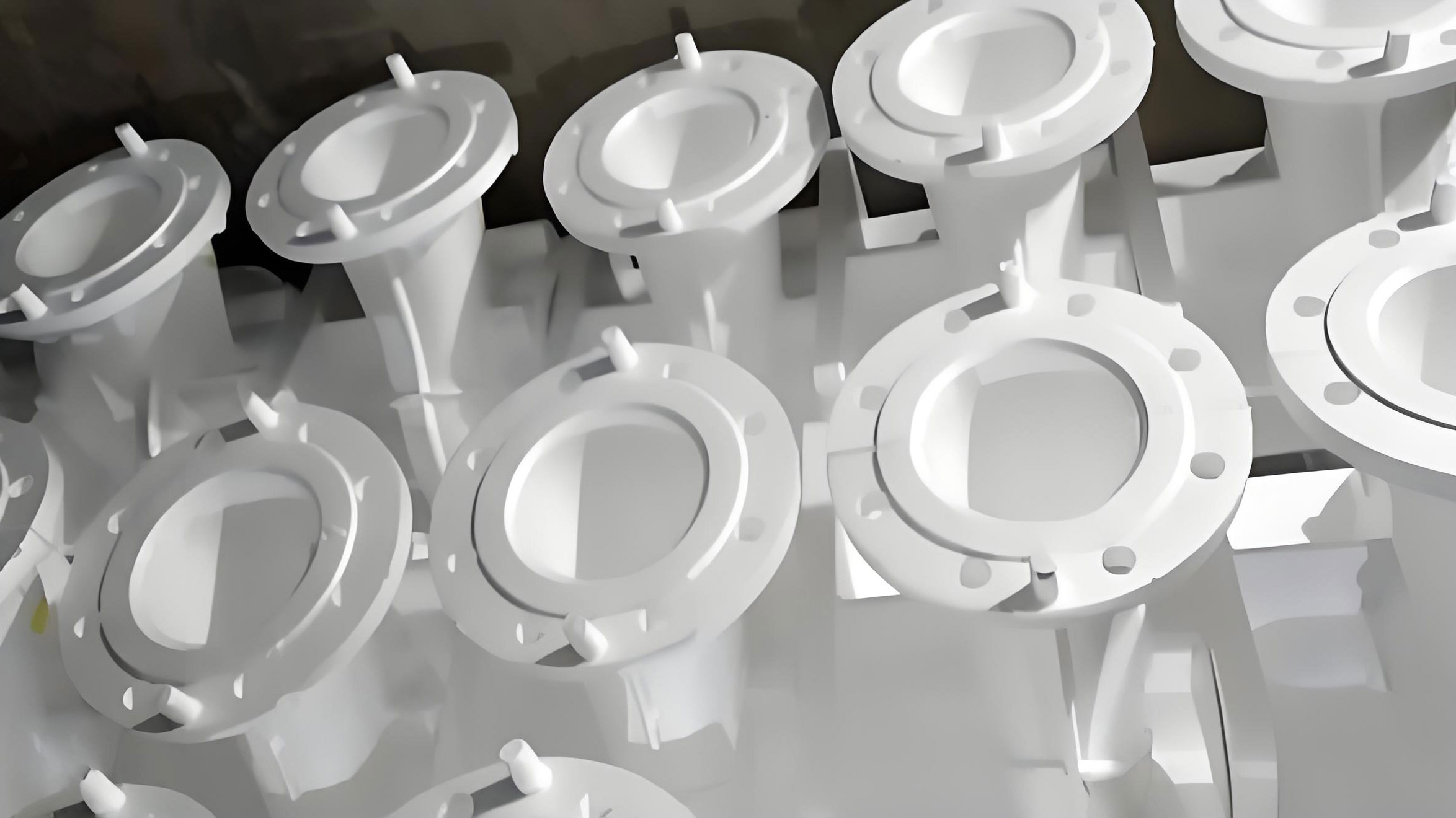
The functional requirements I established are summarized below. These requirements drove both the casting geometry and the process windows.
| Requirement Area | Functional Need | Manufacturing Consequence |
|---|---|---|
| Structural integrity | Resist rod-drop impact without cracking or permanent deformation | Sound internal structure, radiographic acceptance, controlled grain structure |
| Dimensional accuracy | Maintain bore alignment, flatness, perpendicularity, and hole position | Precision pattern tooling, ceramic shell stability, dedicated machining fixtures |
| Flow area | Provide four large flow openings without blockage | Robust core or pattern removal, no shell debris, clean passages |
| Assembly interfaces | Locate twenty-four holes relative to datum cylinder | CNC machining after casting, position tolerance control |
| Corrosion resistance | Withstand reactor water chemistry | CF3 stainless steel chemistry, solution heat treatment |
| Inspectability | Allow penetrant, radiographic, and dimensional inspection | Surface finish, wall access, minimal porosity, clean gates |
I first decomposed the component into castable sections. The modulus method gave me a rapid estimate of feeding requirements. For a casting section, the thermal modulus is
$$M = \frac{V}{A}$$
where \(V\) is the volume of the section and \(A\) is its heat-transfer surface area. A higher modulus means a slower-cooling, heavier section that requires a larger feeder. I used the Chvorinov relation to compare solidification times:
$$t_s = B M^n$$
where \(t_s\) is solidification time, \(B\) is a mold constant, and \(n\) is commonly between 1.5 and 2. For a riser or feed path, I required
$$M_r \geq 1.2 M_c$$
where \(M_r\) is the modulus of the riser or header and \(M_c\) is the modulus of the casting section being fed. This condition helped me avoid shrinkage porosity in the thick cylindrical barrel and in the transition between the barrel and the support plate.
The geometric breakdown I used for casting analysis is shown in the next table. The values are nominal and were used for process planning rather than for final inspection.
| Region | Description | Relative Thickness | Feeding Difficulty | Primary Defect Risk |
|---|---|---|---|---|
| Upper cylindrical bore | Hollow cylinder with larger internal diameter | Thick | High | Shrinkage porosity, bore distortion |
| Conical transition | Tapered passage between upper and lower bores | Medium to thick | Medium | Hot spots, incomplete fusion lines |
| Lower cylindrical bore | Small-diameter hollow section | Medium | Medium | Mold erosion, gas entrapment |
| Support plate ribs | Square plate with four large flow openings | Thin to medium | Low to medium | Cold shut, misrun |
| Assembly holes | Twenty-four holes in defined pattern | Near-net or machined | Low | Position error, drill breakout |
| Barrel-to-plate joint | Junction of cylinder and plate | Thick | High | Shrinkage cavity, residual stress |
I considered several process families before fixing the route. The comparison included welded fabrication, conventional sand casting, investment casting, and evaporative pattern casting. The table below records the decision logic I used. In evaporative pattern casting, a foam pattern is vaporized by the incoming liquid metal, so the pattern is not removed before pouring. In my wax-based investment route, the pattern is removed before pouring, and a ceramic shell remains. Both approaches can produce complex, integrated geometry, but they differ in surface finish, internal quality, tooling, and process control.
| Process | Pattern Material | Pattern Removal | Typical Surface Finish | Internal Quality Potential | Suitability for This Part |
|---|---|---|---|---|---|
| Welded fabrication | None | Not applicable | Machined surfaces | Weld defects possible | Baseline, but joints reduce integral strength |
| Sand casting | Sand mold | Mold shakeout | Rough | Moderate | Poor for thin ribs and fine holes |
| Investment casting | Wax | Steam autoclave | Good to excellent | High when properly fed | Selected route |
| Evaporative pattern casting | Foam | Vaporized by metal | Moderate to good | Good if coating and sand are controlled | Viable alternative, but less favorable for radiographic cleanliness here |
I selected silica-sol investment casting because the component requires fine surface detail, thin rib definition, and reliable radiographic soundness. At the same time, I kept evaporative pattern casting in the trade study because it offers a compelling route for integrated parts with complex internal passages. In an evaporative pattern casting line, the foam pattern can be molded as a single piece, coated, embedded in dry sand, and poured directly. That eliminates wax injection, shell building, and steam dewaxing. However, the decomposition products of the foam can interact with the metal front, and the coating permeability must be carefully balanced. For a safety-critical reactor internal, I judged that the wax-based route gave me tighter control over shell integrity and inclusion prevention. I would still consider evaporative pattern casting for lower-pressure, less critical variants or for larger producible geometries where tooling cost and cycle time dominate.
1. Pattern Tooling and Mold Design
I divided the wax pattern tooling into a cylindrical product section and a main body section. This split simplified mold construction, allowed reliable extraction, and reduced the risk of wax distortion. The cylindrical section was relatively thick, so I used a cold-wax core to accelerate cooling and reduce shrinkage. The main body contained the support plate, ribs, and flow openings. I also integrated the pouring gate into the pattern tooling so that each wax pattern could be assembled into the tree without additional gate fabrication.
For pattern dimensions, I applied a shrinkage allowance based on the difference between the metal contraction and the pattern contraction. A simplified linear relation is
$$L_m = L_c \left(1 + \alpha_s\right)$$
where \(L_m\) is the mold or pattern dimension, \(L_c\) is the desired casting dimension, and \(\alpha_s\) is the net shrinkage allowance. For the alloy and shell system I used, the total allowance was distributed across pattern, shell, and cooling stages. I also used a directional allowance for the bore so that machining would not remove an excessive amount of wall thickness.
| Tooling Element | Design Choice | Reason |
|---|---|---|
| Upper cylindrical cavity | Split insert with cold-wax core | Accelerate cooling, limit shrinkage |
| Conical transition | Replaceable insert | Ease extraction, protect critical taper |
| Lower cylindrical bore | Core pin with draft | Prevent wax tearing during removal |
| Support plate | Two-part body cavity | Simplify mold and avoid undercuts |
| Flow openings | Metal inserts | Maintain opening size and position |
| Assembly holes | Cast pads, later machined | Avoid fragile wax pins and shell cracks |
| Gate | Integrated in tooling | Ensure consistent tree assembly |
The shrinkage allowance I used is summarized below. These values were adjusted after first-article measurement.
| Direction | Nominal Allowance | Purpose |
|---|---|---|
| Axial barrel length | 1.8% to 2.2% | Compensate metal contraction |
| Radial bore | 1.5% to 2.0% | Maintain machining stock |
| Plate length and width | 1.6% to 2.0% | Control flatness and hole pattern |
| Rib thickness | 0.8% to 1.2% | Prevent thin-section mismatch |
| Gate and header | 2.0% to 3.0% | Maintain feed volume |
2. Wax Injection and Pattern Conditioning
Wax injection is the first point where dimensional variation enters the process. I controlled storage temperature, injection-cylinder temperature, injection time, pressure, and cooling method. The table below lists the production window I established.
| Parameter | Requirement | Parameter | Requirement |
|---|---|---|---|
| Wax storage temperature | \(72 \pm 3\,^\circ\text{C}\) | Date marking | None |
| Injection cylinder temperature | \(52 \pm 2\,^\circ\text{C}\) | Nameplate | None |
| Injection time | 30 to 40 s | Wax block addition | No |
| Cooling time | 0 s | Ceramic or urea core | None |
| Injection pressure | \(22\) to \(25\,\text{kg/cm}^2\) | Wax shaping fixture | None |
| Cooling method | Water cooling | Placement | Orderly arrangement |
I converted the injection pressure to SI units for process documentation:
$$1\,\text{kg/cm}^2 = 0.0980665\,\text{MPa}$$
$$22\,\text{kg/cm}^2 \approx 2.16\,\text{MPa}, \quad 25\,\text{kg/cm}^2 \approx 2.45\,\text{MPa}$$
The flow behavior of wax during injection can be approximated by a capillary-flow relation:
$$P = \frac{128 \mu L Q}{\pi D^4}$$
where \(P\) is pressure drop, \(\mu\) is dynamic viscosity, \(L\) is flow length, \(Q\) is volumetric flow rate, and \(D\) is channel diameter. This relation explains why small gates and thin ribs require higher injection pressure. It also explains why I avoided excessive pressure: high shear can fold cold wax and create surface defects.
I also estimated the Reynolds number for the wax flow:
$$Re = \frac{\rho v D}{\mu}$$
For wax injection, the flow is generally laminar or near-laminar. When \(Re\) is low, viscous forces dominate, and the pattern fills smoothly if the temperature is uniform. When the temperature is too low, viscosity rises sharply, and short shots or surface ripples appear. When the temperature is too high, wax shrinkage increases and the pattern becomes more prone to sink marks.
After ejection, I placed the wax patterns in water for uniform cooling. Once fully cooled, I arranged them in orderly trays to prevent impact damage. During wax repair, I removed the parting line and blended the surface until no tool marks remained. I then assembled the split wax sections. The locating features had to align completely. I used bonding wax and hot wax to fuse the sections. After cooling, I scraped excess wax until the surface was smooth. I did not permit depressions or raised spots on the product surface because they would replicate into the shell and then into the casting.
3. Tree Assembly
The tree design was critical for directional solidification. I used a cross-shaped header so that the main sprue would contain enough liquid metal to feed the barrel and the plate. The small gates around the periphery supplied the thinner ribs and plate sections. The tree had to be clean, dry, and free from wax droplets, virtual welds, gaps, and flash. I did not allow water to remain on the pattern or header during assembly. The test coupon was placed in the longitudinal direction of the tree so that it would represent the same thermal history as the product.
The feed volume requirement can be expressed as
$$m_h \geq k m_c$$
where \(m_h\) is the mass of the header or feed section, \(m_c\) is the mass of the casting, and \(k\) is a safety factor. For this geometry, I used \(k\) between 1.5 and 2.5, depending on the local modulus. The cross-shaped header provided a large central reservoir and four directional branches, which improved filling and reduced the risk of isolated hot spots.
| Tree Feature | Design Description | Function |
|---|---|---|
| Main header | Cross-shaped wax bar assembly | Store feed metal, reduce shrinkage |
| Primary sprue | Vertical ceramic-lined channel | Deliver metal smoothly |
| Secondary gates | Uniform peripheral gates | Feed thin plate ribs |
| Pattern orientation | Barrel vertical, plate horizontal or slightly inclined | Promote directional solidification |
| Test coupon | Longitudinal bar attached to tree | Represent mechanical properties |
| Tree density | Even spacing, no contact | Uniform shell drying and metal flow |
4. Shell Making
Shell making determines surface finish, dimensional stability, and resistance to metal erosion. I controlled slurry viscosity with a Zahn cup and maintained the specified temperature and humidity. The face coat used zircon flour and zircon sand because it provides a smooth surface and high refractoriness. Backup layers used mullite flour and mullite sand. The shell was built in multiple layers, with each layer dried under controlled conditions.
The viscosity measured by a Zahn cup can be related to efflux time:
$$\eta = K \rho \left(t – t_0\right)$$
where \(\eta\) is the apparent viscosity, \(K\) is a cup constant, \(\rho\) is density, \(t\) is efflux time, and \(t_0\) is a reference time. I used efflux time as the practical control variable. If the slurry was too thin, the face coat would be weak and the surface would be rough. If it was too thick, the slurry would drain poorly and form lumps.
Shell thickness growth can be approximated by
$$h = k \sqrt{t_d}$$
where \(h\) is layer thickness, \(k\) is a kinetic constant, and \(t_d\) is drying time. I used this relation qualitatively to ensure that each layer had enough dwell time before the next dip. The table below shows the shell-building parameters I established.
| Layer | Slurry Material | Viscosity | Sand Material | Room Temperature | Humidity | Drying Time |
|---|---|---|---|---|---|---|
| Face | Zircon flour | 36 to 40 s | Zircon sand, 80 to 120 mesh | 20 to 26 °C | 60% to 70% RH | 6 to 12 h |
| Second | Mullite flour | 20 to 24 s | Mullite sand, 60 to 80 mesh | 20 to 26 °C | 40% to 60% RH | ≥4 h |
| Third | Mullite flour | 12 to 16 s | Mullite sand, 16 to 30 mesh | 20 to 26 °C | 40% to 60% RH | ≥4 h |
| Fourth | Mullite flour | 12 to 16 s | Mullite sand, 16 to 30 mesh | 20 to 26 °C | 40% to 60% RH | ≥4 h |
| Fifth | Mullite flour | 12 to 16 s | Mullite sand, 16 to 30 mesh | 20 to 26 °C | 40% to 60% RH | ≥4 h |
| Seal | Mullite flour | 8 to 12 s | No sand | 20 to 26 °C | 40% to 60% RH | ≥4 h |
After the second layer, I used robotic shelling. The robot reduced labor intensity, produced a more uniform shell thickness, and improved shell density. The fast-drying room shortened the drying cycle. In many cases, the shell could be taken offline after approximately 24 h, which is a fraction of the conventional manual cycle. This improvement increased productivity and reduced the chance of handling damage. I monitored slurry viscosity daily and adjusted it with distilled water and binder. I also checked sand quality, because contaminated sand can cause shell cracks and inclusions.
| Factor | Manual Shelling | Robotic Shelling |
|---|---|---|
| Labor intensity | High | Low |
| Shell thickness uniformity | Variable | More uniform |
| Shell density | Acceptable | Slightly better |
| Working time | Limited by operator fatigue | Continuous, 24 h capability |
| Drying cycle | Longer | Shortened by fast dryer |
| Reproducibility | Operator dependent | Program controlled |
5. Dewaxing
After the shell was dry, I removed the wax in a steam autoclave. The investment casting route, unlike evaporative pattern casting, removes the pattern before pouring. This gives the ceramic shell an empty cavity and allows the metal to fill a clean mold. In evaporative pattern casting, the foam pattern remains in the mold and is vaporized by the metal. For this safety-critical part, I preferred the empty-cavity approach because it gave me better control over shell cleanliness and internal radiographic quality.
The wax mass to be removed is
$$m_w = \rho_w V_w$$
where \(\rho_w\) is wax density and \(V_w\) is pattern volume. The autoclave energy must be sufficient to melt and displace this wax without damaging the shell. I controlled pressure, vent time, dewaxing time, and temperature. The table below shows the dewaxing parameters.
| Parameter | Requirement |
|---|---|
| Placement | Pouring cup downward |
| Pressure | 0.5 to 0.6 MPa |
| Pressure release time | >50 s |
| Dewaxing time | 10 to 15 min |
| Temperature | 150 to 160 °C |
Before dewaxing, I cleaned flash from the pouring cup. After dewaxing, I placed the shell with the pouring cup downward to prevent dust from entering the cavity. I inspected and cleaned the filter screen regularly and replaced it when necessary. A clean shell cavity is essential for radiographic acceptance. Any residual wax, ash, or loose sand becomes a source of inclusion or gas porosity.
6. Melting and Pouring
Melting and pouring are the most influential steps for internal quality. The component material was CF3 cast steel, a low-carbon stainless steel with good corrosion resistance. I controlled charge composition, furnace cleanliness, deoxidation, and pouring temperature. The table below gives the nominal chemistry control targets I used.
| Element | Nominal Range | Role |
|---|---|---|
| C | ≤0.03% | Corrosion resistance, low carbide precipitation |
| Mn | ≤1.50% | Deoxidation, strength |
| Si | ≤1.50% | Deoxidation, castability |
| P | ≤0.04% | Impurity control |
| S | ≤0.04% | Hot cracking control |
| Cr | 17.0% to 21.0% | Passivation, corrosion resistance |
| Ni | 8.0% to 12.0% | Austenite stability, toughness |
| Mo | ≤0.50% | Optional residual control |
I cleaned the furnace completely before melting. Residual slag and steel from previous heats can alter chemistry and introduce inclusions. I followed the material batching sheet strictly. The barrel is long, and the plate ribs are thin, so the filling and feeding behavior vary across the part. A single pouring temperature must satisfy both the heavy section and the thin section. I selected \(1\,550 \pm 10\,^\circ\text{C}\). At lower temperatures, the thin ribs risk cold shut and misrun. At higher temperatures, the heavy barrel risks shrinkage, gas absorption, and shell erosion.
The heat transfer from the metal to the shell can be written as
$$q = h A \left(T_m – T_s\right)$$
where \(q\) is heat flux, \(h\) is the interfacial heat-transfer coefficient, \(A\) is area, \(T_m\) is metal temperature, and \(T_s\) is shell temperature. A high \(h\) increases cooling rate. I used a wet sand bed at the lower half of the shell to accelerate cooling in the lower region. I wrapped the header with insulation to keep it hot and maintain a feed path. This combination produced a thermal gradient favorable for directional solidification.
The temperature gradient during solidification is approximated by
$$G = \frac{T_m – T_s}{x}$$
where \(x\) is distance along the feed path. A positive gradient from the casting to the header helps feed shrinkage. I also estimated the feeding distance:
$$L_f = k \sqrt{M}$$
where \(L_f\) is the effective feeding distance and \(k\) is an empirical constant. This relation guided gate placement and header size.
| Parameter | Requirement |
|---|---|
| Baking temperature | \(1\,100 \pm 20\,^\circ\text{C}\) |
| Baking time | ≥90 min |
| New-to-old charge ratio | ≥60:40 |
| Pouring temperature | \(1\,550 \pm 10\,^\circ\text{C}\) |
| Slag removal | Electrostatic slagging |
| Deoxidation additions | Electrolytic manganese, ferrosilicon, calcium-silicon, 50 to 70 g each |
| Insulating agent | Yes |
| Box clamping | No |
| Cooling method | Wet sand bed |
During pouring, I used a smooth, controlled stream to avoid turbulence and gas entrainment. The mold was positioned so that the barrel filled progressively and the plate ribs filled from the gates. After pouring, the shell was placed on the wet sand bed so that the lower region cooled first. The header was covered with insulation so that it cooled last. This is a practical application of the modulus and Chvorinov concepts. In effect, I created a thermal hierarchy: thin ribs, plate, barrel, gate, header. If the hierarchy is reversed, the header freezes first and the casting cannot be fed.
I also considered how evaporative pattern casting would behave in this step. In evaporative pattern casting, the foam pattern decomposes as the metal advances, generating gas that must escape through the coating and sand. That gas evolution can perturb the fill front and increase the risk of gas porosity. In my investment casting route, the shell cavity is empty before pouring, so the fill front is not influenced by pattern decomposition. This difference was a major reason I chose the wax-based investment route for the guide support. I still value evaporative pattern casting for its simplicity and design freedom, but for this class of component I required the cleaner cavity.
7. Heat Treatment
After knockout and cut-off, the castings were heat treated. The material required solution treatment. I used a sealed, well-controlled pit-type resistance furnace with air atmosphere. The holding temperature was \(1\,100\,^\circ\text{C}\), and the holding time was 80 min. The parts were arranged uniformly and not stacked, so that each part saw the same thermal cycle. After soaking, the parts were quenched rapidly in water. The initial water temperature was not more than \(50\,^\circ\text{C}\). The parts remained in the water until fully cooled.
The cooling rate during quenching can be approximated by
$$\dot{T} = \frac{dT}{dt} \approx \frac{T – T_q}{\tau}$$
where \(T\) is the instantaneous part temperature, \(T_q\) is the quenchant temperature, and \(\tau\) is a thermal time constant. A smaller \(\tau\) means faster cooling. Rapid cooling suppresses carbide precipitation and improves corrosion resistance, but it also creates thermal stress. I controlled the quench by ensuring uniform immersion and avoiding part-to-part contact.
The temperature history can be summarized by a heat-treatment curve. The table below gives the key set points.
| Stage | Parameter | Value |
|---|---|---|
| Heating | Target temperature | \(1\,100 \pm 20\,^\circ\text{C}\) |
| Soaking | Holding time | 80 min |
| Quenching | Medium | Water |
| Quenching | Initial water temperature | ≤50 °C |
| Cooling | Final condition | Fully cooled before removal |
| Furnace | Type | Sealed pit-type resistance furnace |
8. Machining
After heat treatment, I machined the support plate faces, the guide barrel, and the twenty-four assembly holes. The main challenge was to maintain the position of the twenty-four holes relative to datum cylinder A. Because the part geometry is asymmetric and the plate is relatively flexible, I designed a dedicated machining fixture. The fixture supported the plate from below and clamped the barrel without distortion. This allowed the CNC lathe to turn the cylindrical features and the machining center to drill, ream, and countersink the holes.
Position error in the plane can be expressed as
$$e_p = \sqrt{e_x^2 + e_y^2}$$
where \(e_x\) and \(e_y\) are the errors in two orthogonal directions. The total position tolerance can be estimated by
$$T_{pos} = \sqrt{T_x^2 + T_y^2 + T_z^2}$$
where \(T_x\), \(T_y\), and \(T_z\) are the component tolerances. I used this relation to allocate tolerance among casting, fixture, and machining. The casting was designed with sufficient machining stock so that the final dimensions could be achieved without exposing porosity.
| Operation | Machine | Feature | Control Method |
|---|---|---|---|
| Rough turning | CNC lathe | Barrel outer diameter and bores | Datum setup, dial indicator |
| Finish turning | CNC lathe | Upper bore, taper, lower bore | In-process gauging |
| Face milling | Machining center | Support plate top and bottom | Flatness check |
| Hole drilling | Machining center | Twenty-four assembly holes | Fixture with hardened bushings |
| Reaming | Machining center | Hole diameter and finish | Go/no-go gauges |
| Deburring | Manual station | Edges and passages | Visual and penetrant inspection |
The machining fixture ensured the perpendicularity of datum cylinder A to datum plane C. It also ensured the position of the twenty-four holes. I verified the fixture with a coordinate measuring machine before production. During production, I used statistical process control to monitor hole position, bore diameter, and flatness. If a trend appeared, I corrected the fixture or the machine offset before the process moved outside the control limits.
9. Inspection and Testing
I subjected the first-article castings and production samples to a comprehensive inspection plan. The plan included chemical composition analysis, metallography, penetrant testing, radiographic testing, intergranular corrosion testing, mechanical property testing, and hardness testing. The results had to meet the drawing technical conditions. The table below summarizes the inspection methods and their purposes.
| Inspection | Purpose | Method | Acceptance Focus |
|---|---|---|---|
| Chemical analysis | Verify CF3 chemistry | Optical emission spectrometry | Element ranges |
| Metallography | Evaluate microstructure | Microscopy | Austenite, inclusions, carbides |
| Penetrant testing | Detect surface defects | Liquid penetrant | No relevant indications |
| Radiographic testing | Detect internal defects | X-ray or gamma ray | No shrinkage, gas, inclusions above limits |
| Intergranular corrosion | Verify corrosion resistance | Standard corrosion test | No sensitization |
| Mechanical testing | Verify strength and ductility | Tensile test | Yield, ultimate, elongation |
| Hardness testing | Verify heat treatment | Rockwell or Brinell | Specified range |
I used process capability indices to judge whether the process could meet tolerances. For a critical dimension,
$$C_{pk} = \min\left(\frac{USL – \mu}{3\sigma}, \frac{\mu – LSL}{3\sigma}\right)$$
where \(USL\) is the upper specification limit, \(LSL\) is the lower specification limit, \(\mu\) is the process mean, and \(\sigma\) is the process standard deviation. I required \(C_{pk} \geq 1.33\) for critical features such as bore diameter and hole position. For non-critical features, I required \(C_{pk} \geq 1.00\). When \(C_{pk}\) was below target, I investigated the pattern tooling, shell distortion, heat treatment distortion, and machining fixture.
The overall process yield is
$$Y = \frac{N_{good}}{N_{total}} \times 100\%$$
where \(N_{good}\) is the number of conforming castings and \(N_{total}\) is the total number produced. I tracked yield by defect category so that improvements could be focused on the dominant loss. The table below shows the defect modes I monitored and the countermeasures I applied.
| Defect Mode | Likely Cause | Countermeasure |
|---|---|---|
| Shrinkage porosity | Insufficient feed, poor thermal gradient | Increase header modulus, adjust insulation, optimize gate location |
| Gas porosity | Turbulent pouring, shell gas, wax residue | Improve pouring, clean shell, extend dewaxing |
| Cold shut | Low pouring temperature, thin ribs | Raise temperature within window, increase gate size |
| Misrun | Slow fill, low superheat | Improve fill path, increase pouring rate |
| Shell crack | Weak slurry, handling damage, uneven drying | Control viscosity, robot handling, humidity control |
| Inclusion | Loose sand, slag, reoxidation | Clean furnace, filter, improve shell cleanliness |
| Dimensional drift | Wax shrink, shell expansion, quench distortion | Tooling correction, fixture control, heat treatment support |
| Hole position error | Fixture wear, datum shift | Regular fixture calibration, CMM verification |
10. Evaporative Pattern Casting as a Comparative Benchmark
I maintained an explicit comparison with evaporative pattern casting throughout the project. Evaporative pattern casting is attractive because it eliminates the wax injection, shell building, and dewaxing steps. A foam pattern is molded, coated, embedded in unbonded sand, and poured. The metal vaporizes the foam and fills the cavity. This route can produce complex, integrated parts with fewer process steps. In many industrial applications, evaporative pattern casting reduces tooling cost and cycle time. However, the process has different physical phenomena at the mold-metal interface. The foam decomposition produces gas and liquid residues, and the coating must allow the gas to escape while resisting metal penetration. If the coating is too permeable, metal can penetrate the sand. If it is too tight, gas defects can form.
The foam mass that must be vaporized is
$$m_f = \rho_f V_f$$
where \(\rho_f\) is foam density and \(V_f\) is pattern volume. The energy required to decompose the foam includes heating and latent effects:
$$E_g = c_p \Delta T + L_v$$
where \(c_p\) is specific heat, \(\Delta T\) is temperature rise, and \(L_v\) is latent heat of vaporization or decomposition. This energy is absorbed from the incoming metal, which locally reduces the metal temperature. For thin sections, that local cooling can cause cold shuts. For thick sections, the gas must escape before it becomes trapped. In my investment casting route, the cavity is empty, so these phenomena do not occur. This is a key reason I chose investment casting for the guide support. The comparison table below summarizes the differences.
| Attribute | Investment Casting with Wax | Evaporative Pattern Casting |
|---|---|---|
| Pattern material | Wax | Foam |
| Pattern removal | Steam autoclave before pouring | Vaporized during pouring |
| Mold material | Ceramic shell | Refractory-coated sand |
| Surface finish | Excellent | Good |
| Internal cleanliness | High, empty cavity | Dependent on coating and gas escape |
| Tooling cost | Higher | Lower for some geometries |
| Cycle time | Longer | Shorter |
| Complex internal passages | Excellent with soluble cores or preforms | Excellent if foam can be molded and removed |
| Best fit for this component | Selected for safety-critical quality | Benchmark alternative for future variants |
I also evaluated whether the guide support could be converted to evaporative pattern casting in a future production cell. The main changes would be foam pattern tooling, coating formulation, sand compaction, and pouring control. The design would need to avoid sharp internal corners that trap decomposition gas. The coating would need a graded permeability. The pouring temperature and fill rate would need to be optimized to balance foam decomposition and metal fluidity. Even though I selected investment casting, evaporative pattern casting remains a valid reference for cost reduction and process simplification. I use it as a benchmark whenever I review the value stream.
11. Process Control and Repeatability
I established a process control plan that covered incoming materials, wax injection, shell building, dewaxing, melting, pouring, heat treatment, machining, and inspection. Each critical parameter had a target, a tolerance, a measurement method, and a reaction plan. The table below shows the main control points.
| Stage | Critical Parameter | Control Method | Reaction Plan |
|---|---|---|---|
| Wax injection | Temperature, pressure, time | Machine recorder, periodic check | Adjust machine, quarantine affected patterns |
| Wax assembly | Alignment, fusion, surface | Visual, gauge | Rework or scrap |
| Shell building | Viscosity, humidity, drying | Zahn cup, hygrometer, timer | Adjust slurry, extend drying |
| Dewaxing | Pressure, temperature, time | Autoclave controller | Reject shells with residue or cracks |
| Melting | Chemistry, temperature | Spectrometer, thermocouple | Re-batch or correct chemistry |
| Pouring | Temperature, fill rate | Pyrometer, visual | Stop, adjust, isolate heat |
| Heat treatment | Temperature, time, quench | Furnace chart, water temperature | Re-heat-treat if allowed, otherwise scrap |
| Machining | Position, flatness, bore size | CMM, gauges | Offset correction, fixture repair |
I used first-article inspection to validate the entire chain. The first article was measured dimensionally, radiographed, penetrant inspected, and sectioned for metallography. After approval, I moved to production with a reduced but still rigorous inspection plan. Critical features remained at 100% inspection until the process capability was demonstrated. For non-critical features, I used sampling. This approach balanced quality and cost.
12. Dimensional and Metallurgical Relationships
Several quantitative relationships helped me make decisions. I list them here for completeness.
Thermal expansion during heating or cooling:
$$\Delta L = \alpha L \Delta T$$
where \(\Delta L\) is change in length, \(\alpha\) is coefficient of thermal expansion, \(L\) is original length, and \(\Delta T\) is temperature change. This relation was used to estimate pattern shrinkage, shell expansion, and quench distortion.
Solidification modulus:
$$M = \frac{V}{A}$$
Chvorinov solidification time:
$$t_s = B M^n$$
Riser modulus requirement:
$$M_r \geq 1.2 M_c$$
Volumetric flow rate during pouring:
$$Q = \frac{V}{t_p}$$
where \(V\) is the mold cavity volume and \(t_p\) is pouring time. A controlled pouring time helps avoid turbulence and cold shuts.
Bernoulli-like sprue flow:
$$v = \sqrt{2 g h}$$
where \(v\) is velocity, \(g\) is gravitational acceleration, and \(h\) is effective head. This relation helped me size the sprue and avoid excessive velocity.
Heat flux during solidification:
$$q = h A \left(T_m – T_s\right)$$
Temperature gradient:
$$G = \frac{T_m – T_s}{x}$$
Cooling rate during quenching:
$$\dot{T} = \frac{dT}{dt} \approx \frac{T – T_q}{\tau}$$
Position error:
$$e_p = \sqrt{e_x^2 + e_y^2}$$
Total position tolerance:
$$T_{pos} = \sqrt{T_x^2 + T_y^2 + T_z^2}$$
Process capability:
$$C_{pk} = \min\left(\frac{USL – \mu}{3\sigma}, \frac{\mu – LSL}{3\sigma}\right)$$
Process yield:
$$Y = \frac{N_{good}}{N_{total}} \times 100\%$$
These equations are not a substitute for experimentation, but they provided a structured way to set initial process windows. I then refined the windows with trial pours and first-article measurements.
13. Results and Validation
The castings produced by the selected route were subjected to chemical analysis, metallography, penetrant testing, radiographic testing, intergranular corrosion testing, mechanical property testing, and hardness testing. The results met the drawing technical conditions. The barrel bores were concentric after machining. The support plate flatness and perpendicularity were within tolerance. The twenty-four holes met their position requirements relative to datum cylinder A. Radiographic inspection showed no relevant internal defects above the acceptance limit. The heat-treated microstructure was consistent with the expected CF3 stainless steel condition. The mechanical properties and hardness were within the specified ranges.
I also compared the cast-and-machined route with the previous welded fabrication route. The cast route reduced the number of joints, eliminated weld heat-affected zones in the load path, and provided a more continuous material structure. The cast route required more upfront tooling and process development, but it offered better repeatability once the process was mature. The table below summarizes the comparison.
| Attribute | Welded Fabrication | Precision Casting Route |
|---|---|---|
| Number of joints | Multiple | None in the main load path |
| Heat-affected zones | Present | Eliminated |
| Material continuity | Interrupted | Continuous |
| Dimensional repeatability | Dependent on fixture and weld distortion | Dependent on pattern and shell control |
| Inspection burden | Weld inspection | Radiography, penetrant, dimensional |
| Strength in load path | Limited by weld properties | Uniform cast properties after heat treatment |
| Tooling cost | Lower | Higher |
| Production efficiency at scale | Moderate | High after process maturity |
14. Scale-Up and Future Improvements
The initial production used a header made from existing wax bars. This was acceptable for development, but it made the tree structure complex and reduced efficiency. For batch production, I recommended a dedicated header die. A dedicated die would simplify tree assembly, reduce wax consumption, improve feed consistency, and increase yield. I also recommended further automation of wax assembly and shell handling. Robotic shelling already improved uniformity and reduced labor. The next step would be automatic slurry viscosity control and automatic drying-room loading.
I also evaluated evaporative pattern casting for future variants. If the production volume increased and the quality requirements allowed, evaporative pattern casting could reduce cycle time and tooling cost. However, the foam pattern would need a robust coating and a well-controlled sand system. The pouring process would need to be optimized for foam decomposition. I would not replace the current investment casting route without a full qualification program, because the current route has demonstrated radiographic quality and dimensional capability. I would treat evaporative pattern casting as a parallel development path rather than an immediate substitution.
The table below lists the improvement opportunities I identified.
| Opportunity | Expected Benefit | Risk | Action |
|---|---|---|---|
| Dedicated header die | Simpler tree, higher yield | Tooling cost | Design and qualify |
| Automated wax assembly | Less variation, higher throughput | Capital cost | Pilot cell |
| Automatic slurry control | Stable shell quality | Maintenance | Install sensors |
| Evaporative pattern casting trial | Lower cycle time, lower tooling cost | Gas defects, coating control | Prototype study |
| In-line CMM | Faster feedback on hole position | Cost | Evaluate for critical features |
| Digital process records | Traceability and trend analysis | Data integration | Implement MES module |
15. Concluding Perspective
I developed a precision casting route for a compression system guide support that integrates a hollow guide barrel and a perforated support plate into a single component. The route uses wax pattern injection, silica-sol shell building, steam dewaxing, CF3 stainless steel melting, controlled pouring, solution heat treatment, and CNC machining. The process windows for wax injection, shell building, dewaxing, melting, pouring, and heat treatment were established and documented. The castings met chemical, metallurgical, radiographic, penetrant, mechanical, hardness, and dimensional requirements. The integral cast design removes weld joints from the primary load path and improves structural continuity.
I also maintained a thorough comparison with evaporative pattern casting. Evaporative pattern casting offers a compelling alternative for integrated components because it eliminates wax and shell steps, but it introduces foam decomposition and gas-escape challenges. For this safety-critical guide support, I selected investment casting because the empty ceramic cavity provided superior control over internal cleanliness and radiographic quality. I continue to view evaporative pattern casting as a valuable benchmark and a potential future route for less critical or higher-volume variants. The methods, tables, and equations presented here can be adapted to similar components that require precision casting, integrated geometry, and reliable structural performance.