
Emergency diesel generator sets are a critical defense line for the safe and stable operation of nuclear power plants. When both the normal daily power supply and the safety auxiliary power supply fail, the emergency diesel unit must start within 10 s and reach rated speed and rated voltage to satisfy the emergency power supply demand. During the slow shutdown stage, the reactor core must be fully cooled to ensure safe reactor shutdown. The water circulation system of the emergency diesel generator set includes an electric pump for high-temperature water preheating and an electric pump for low-temperature water circulation cooling. These two pumps, as the preheating and cooling system of the emergency diesel generator set, can guarantee that the generator is in a hot standby state during operation and can safely and smoothly reach the shutdown state during shutdown. They are among the most critical auxiliary equipment in the generator set. The water circulation electric pump of the emergency generator set is usually a centrifugal water pump with a relatively small flow rate. In the pump unit, the pump case is the main place for medium transmission and energy conversion. Its internal flow passage not only bears the corrosion of the fluid medium but also suffers from high-pressure and high-speed load impact. Therefore, the flow passage design, material selection, and forming method of the pump case are key links in the production and manufacturing of centrifugal water pumps. As a common auxiliary equipment in nuclear power plants, the water circulation pump has higher reliability requirements, and the material is generally selected according to the French RCCM code.
The RCCM—2007 standard, “Design and Construction Rules for Mechanical Components of PWR Nuclear Islands,” was formulated by the French Association for the Design, Construction, and In-Service Inspection of Nuclear Island Equipment. It is one of the internationally accepted codes for the design and construction of pressurized water reactor nuclear power units. Its goal is to establish technical rules for nuclear island equipment according to practice and feedback from industrial experience, so as to ensure the high quality and safety requirements of nuclear reactor operation. For emergency generator sets using seawater as the medium, nuclear power plants commonly use stainless steel with excellent oxidation resistance and corrosion resistance as the pump body material. RCCM—2007 specifies the scope of application and rules for the design, material selection, production and manufacturing, and product inspection of mechanical equipment in PWR nuclear islands. In Volume II, Material Section M, the pressure-retaining castings used in nuclear class 1, 2, and 3 equipment are specified as M3402 austenitic-ferritic stainless steel. This material has strict control of sulfur and phosphorus elements, with \(S \le 0.015wt\%\) and \(P \le 0.030wt\%\), and the mechanical property requirements for castings are relatively high. In summary, the internal flow passage of a centrifugal pump case is complex, the casting difficulty is high, the composition control is strict, and the mechanical property requirements are high, making it one of the difficult points in the manufacturing of nuclear emergency equipment. In this work, starting from actual production, I designed the casting process for an M3402 austenitic-ferritic stainless steel pump case, optimized the process scheme according to trial production results, and then combined ProCAST casting process simulation technology to simulate the mold filling process. Finally, I analyzed and discussed the results by means of production verification. I also considered full mold casting as a comparative route, although the final precision casting route was investment casting with a full mold casting benchmark for thermal and filling analysis.
The pump case casting of the emergency generator set water circulation pump has a mass of about 12 kg. Its maximum outline size is about \(300\,mm \times 140\,mm \times 240\,mm\), its maximum wall thickness is 22 mm, its minimum wall thickness is 3 mm, the inlet flange thickness is 21 mm, and the outlet flange thickness is 19.5 mm. Several ribs connect the structure, and the minimum wall thickness is at the middle pump tongue, with a thickness of 3 mm. The pump case casting has a thin-walled complex fluid curved surface structure. The pump case material selected is M3402 austenitic-ferritic stainless steel, also designated Z3NCD19-10M, as specified in RCCM—2007. The castings were produced by investment casting. Compared with ordinary stainless steel, this material has the good toughness of austenitic steel and the higher strength and chloride stress corrosion resistance of ferritic steel. Compared with pure austenitic stainless steel, it also has better casting fluidity. This combination is important for a pump case with thin walls and thick flanges, and it is also relevant when comparing the process window with full mold casting, because full mold casting can sometimes reduce draft and parting-line constraints but may introduce foam degradation and gas defects.
For the casting process design, I used a medium-frequency electric furnace. A bar stock with a composition close to the target material was remelted. During alloy melting, the content of constituent elements was controlled to prevent chemical composition from exceeding the specification. According to the casting structure, dewaxing, mold filling, and feeding requirements, the pouring system initially adopted a top pouring plus side pouring system. At present, the process yield of the mainstream casting process for pump cases is less than 50%, and the process yield of this casting is about 30%. The pouring system design is shown in the original process layout, but here I summarize the essential dimensions in tables and formulas. For the pump case casting shape and subsequent machining conditions, the outer circle center of the inlet flange (A, C) and the non-machined surface of the inlet flange (B) were selected as the datum. The machining allowance was 3 mm. The main wall thickness of the casting was 3 to 22 mm. Considering the casting material and free shrinkage and restrained shrinkage, the comprehensive shrinkage scale was 2%. This shrinkage scale is a key input for both investment casting and full mold casting tooling, although the shrinkage behavior in full mold casting can differ because of the foam pattern and sand compaction.
To ensure mold filling, casting feeding, and smooth wax removal, a top pouring plus side pouring system was selected, with two pieces per mold. The cross-sectional area of the ingate was determined by the proportional factor method. The hot spot circle diameter at the ingate location was 25 mm. The relationship between the ingate diameter \(D_g\) and the hot spot circle diameter \(D_c\) is:
$$D_g = (0.6 \sim 1.0) D_c$$
Here I took the coefficient as 0.8, and the calculated ingate diameter \(D_g\) was 20 mm. Thus the ingate was determined. The ingate was a wedge-shaped structure, and the number of ingates was four. According to the model dimensions, the bottom edge of the trapezoidal cross-section was 20 mm, the top edge was 25 mm, and the height was 18 mm. This design was intended to promote sequential solidification and to avoid isolated liquid regions. In a full mold casting variant, the same feeding distance criterion would require careful consideration because the foam pattern decomposes during pouring and can alter the local thermal field.
An excessively large sprue increases self-consumption feeding, so under the condition that feeding during solidification is unobstructed, the smaller the sprue cross-section, the better. It is generally determined by:
$$D_s \ge (1.1 \sim 1.2) D_g$$
where \(D_s\) and \(D_g\) are the equivalent hot spot circle diameters of the sprue and ingate cross-sections, respectively. The equivalent hot spot circle diameter of the sprue cross-section was \(D_s = 1.1 \times 20 = 22\) mm, which is the inscribed circle diameter of a square cross-section sprue. Combined with actual production, to ensure module strength and rapid dewaxing to prevent shell cracking, three types of sprues were designed. The sprue cross-section was square, and the dimensions were all \(22\,mm \times 22\,mm\). The pouring cup was designed with a bottom diameter of 50 mm, a top diameter of 140 mm, and a height of 90 mm. These values were used as the initial gating system for the first trial. If full mold casting were used, the pouring cup and sprue would need to be sized for the additional gas evolution from the foam pattern, which is a distinctive feature of full mold casting.
| Parameter | Initial design value | Basis or formula |
|---|---|---|
| Hot spot circle diameter \(D_c\) | 25 mm | Local thermal modulus |
| Ingate diameter \(D_g\) | 20 mm | \(D_g = 0.8 D_c\) |
| Ingate shape | Wedge | Four ingates |
| Trapezoidal bottom edge | 20 mm | From \(D_g\) |
| Trapezoidal top edge | 25 mm | Feeding and filling |
| Trapezoidal height | 18 mm | Gating ratio |
| Sprue equivalent diameter \(D_s\) | 22 mm | \(D_s \ge 1.1 D_g\) |
| Sprue cross-section | \(22\,mm \times 22\,mm\) | Square |
| Pouring cup bottom diameter | 50 mm | Metal head |
| Pouring cup top diameter | 140 mm | Pouring rate |
| Pouring cup height | 90 mm | Filling control |
| Comprehensive shrinkage scale | 2% | Free and restrained shrinkage |
The mold material was forged aluminum. The dimensional precision of the mold was one sixth of the casting dimensional precision. The dimensional precision in the mold cavity met a tolerance of \(\pm 0.03\,mm\), and the profile tolerance of the mold cavity surface met \(\pm 0.03\,mm\). The surface roughness of the mold cavity was required to be \(Ra\,0.8\,\mu m\). Because the casting dimensions and precision requirements are high, wax pattern quality affects casting quality. Therefore, the pattern-making process needed strict control. The wax pattern manufacturing process parameters are given in Table 2. The prepared module was completely immersed in cleaning agent, cleaned for 6 to 9 s each time, repeated three times, and not cleaned for too long to prevent corrosion of the wax pattern. Then the module was immersed in clean water and cleaned reciprocally. After hanging and cleaning, the module was left standing to ensure no residual cleaning agent remained on the surface before entering the next process. In a full mold casting process, the pattern would be a foam pattern rather than a wax pattern, and the cleaning and coating steps would be replaced by foam bead fusion, coating, and drying, but the dimensional precision requirement remains similarly important for full mold casting.
| Parameter | Value | Parameter | Value |
|---|---|---|---|
| Room temperature / °C | 22–25 | Wax tube temperature / °C | 55–65 |
| Cooling water temperature / °C | 17–25 | Wax cylinder temperature / °C | 55–65 |
| Wax injection temperature / °C | 58–60 | Wax injection pressure / MPa | 0.45–0.50 |
| Injection and holding time / s | 40–45 | — | — |
The shell-making process was as follows. The face layer used silica sol and zircon powder or sand, with two face layers. The backing layers, eight and a half layers in total, consisting of two transition layers, six backing layers, and one sealing layer, used silica sol and Shangdian sand or powder. The total number of shell layers was ten and a half. The shell-making process parameters are listed in Table 3. The qualified 316L scrap and returned material were used, with \(S \le 0.015\%\) and \(P \le 0.030\%\). Melting was carried out by remelting. Other elements were adjusted with ferrosilicon, ferromanganese, ferrochromium, ferromolybdenum, and so on. Before pouring, deoxidation and degassing treatment were carried out to ensure that the composition and gas content met the requirements. The shell was roasted in a box-type resistance furnace at \((1050 \pm 10)^\circ C\) for at least 1.5 h. Melting was performed in a medium-frequency induction furnace with thermocouple temperature measurement. The pouring temperature was \((1640 \pm 10)^\circ C\). The solution treatment of the casting was heating to \((1090 \pm 10)^\circ C\), holding for 2 to 2.5 h, and water quenching. These parameters were selected to dissolve carbides and sigma phases and to obtain a balanced austenitic-ferritic microstructure. In a full mold casting route, the pouring temperature and shell or sand temperature would require a different balance because the foam pattern absorbs heat during decomposition, and the gas pressure must be managed to avoid entrapped gas defects.
| Coating type | Face layer | Transition layer | Backing layer | Sealing layer |
|---|---|---|---|---|
| Slurry | Silica sol + zircon powder | Silica sol + Shangdian powder | Silica sol + Shangdian powder | Backing slurry |
| Stucco | 80–120 mesh zircon sand | 30–60 mesh Shangdian sand | 16–30 mesh Shangdian sand | — |
| Temperature / °C | \(24 \pm 2\) | — | ||
| Relative humidity / % | \(65 \pm 5\) | — | ||
| Wind speed / \(m \cdot s^{-1}\) | \(\le 3\) | 6–8 | 6–8 | 6–8 |
| Drying time / h | 6–8 | \(\ge 10\) | \(\ge 12\) | \(\ge 24\) |
| Pre-wetting agent | Immersion pre-wetting agent | — | — | — |
After the first trial, I analyzed the defects and optimized the process. The material and structure of the water circulation pump case show several process difficulties. First, to obtain the non-national-standard composition of RCCM—2007 austenitic-ferritic stainless steel M3402, a medium-frequency electric furnace was used with a bar stock close in composition and remelted. During alloy melting, chemical composition exceeding the standard and poor deoxidation can easily occur. Second, the casting dimensional accuracy must meet CT7 in GB6414, and the surface roughness must not be greater than \(Ra\,12.5\,\mu m\). The casting is large, and the wall thickness varies greatly. During shrinkage, the shrinkage resistance of different parts is different, so the casting dimensions are not easy to guarantee. Third, because the casting is large, the wall thickness difference is large, and there are many isolated hot spots, defects such as porosity, shrinkage, and cracks are likely to appear at the hot spot positions. These difficulties are common to both investment casting and full mold casting, although the specific defect formation mechanisms can differ; in full mold casting, gas defects and carbon pickup are additional concerns.
Based on previous experience in pouring shell-type parts, a horizontal pouring method was used in the first trial, and a stainless steel pump case was obtained. By observation, obvious shrinkage porosity appeared at the neck outlet of the pump case. The application scenario of the emergency diesel generator electric pump determines that the pump case casting must pass strict sealing tests. Defects at the neck of the pump case often lead to sealing test failure, causing the pump case to crack or leak, which would have very serious consequences in actual use. From the above defect analysis, the thickness of the casting in the shrinkage porosity region is relatively large. After the casting surface forms a shell, there is a relatively wide solid-liquid coexistence solidification region inside. As solidification proceeds, the solid fraction increases continuously. Until the late solidification stage, dendrites grow and connect into a skeleton, dividing the remaining liquid metal into isolated or nearly isolated small pools. These liquid pools are difficult to feed during solidification, thus forming shrinkage porosity. From the above casting process design, the horizontal pouring system with top pouring plus side pouring concentrates the last solidified region at the thick outlet part. In addition, the existing pouring system structure is not easy to form an effective feeding effect, so the thick neck region of the pump case does not dissipate heat sufficiently, and shrinkage porosity appears during solidification. According to the structural characteristics of the pump case, a vertical pouring system design was adopted. At the same time, enlarged risers were designed in the thick region, which can better exhaust, collect slag, guide mold filling, achieve better heat dissipation, and avoid hot spots. The optimized pouring system is summarized in Table 4.
| Feature | Initial horizontal top + side pouring | Optimized vertical pouring |
|---|---|---|
| Mold orientation | Horizontal | Vertical |
| Feeding at neck | Weak | Enhanced by risers |
| Hot spot location | Outlet neck | Moved to gating system |
| Gas escape | Moderate | Improved |
| Slag collection | Moderate | Improved |
| Porosity risk | High | Low |
| Full mold casting analogy | Foam gas may be trapped | Foam gas venting easier in vertical orientation |
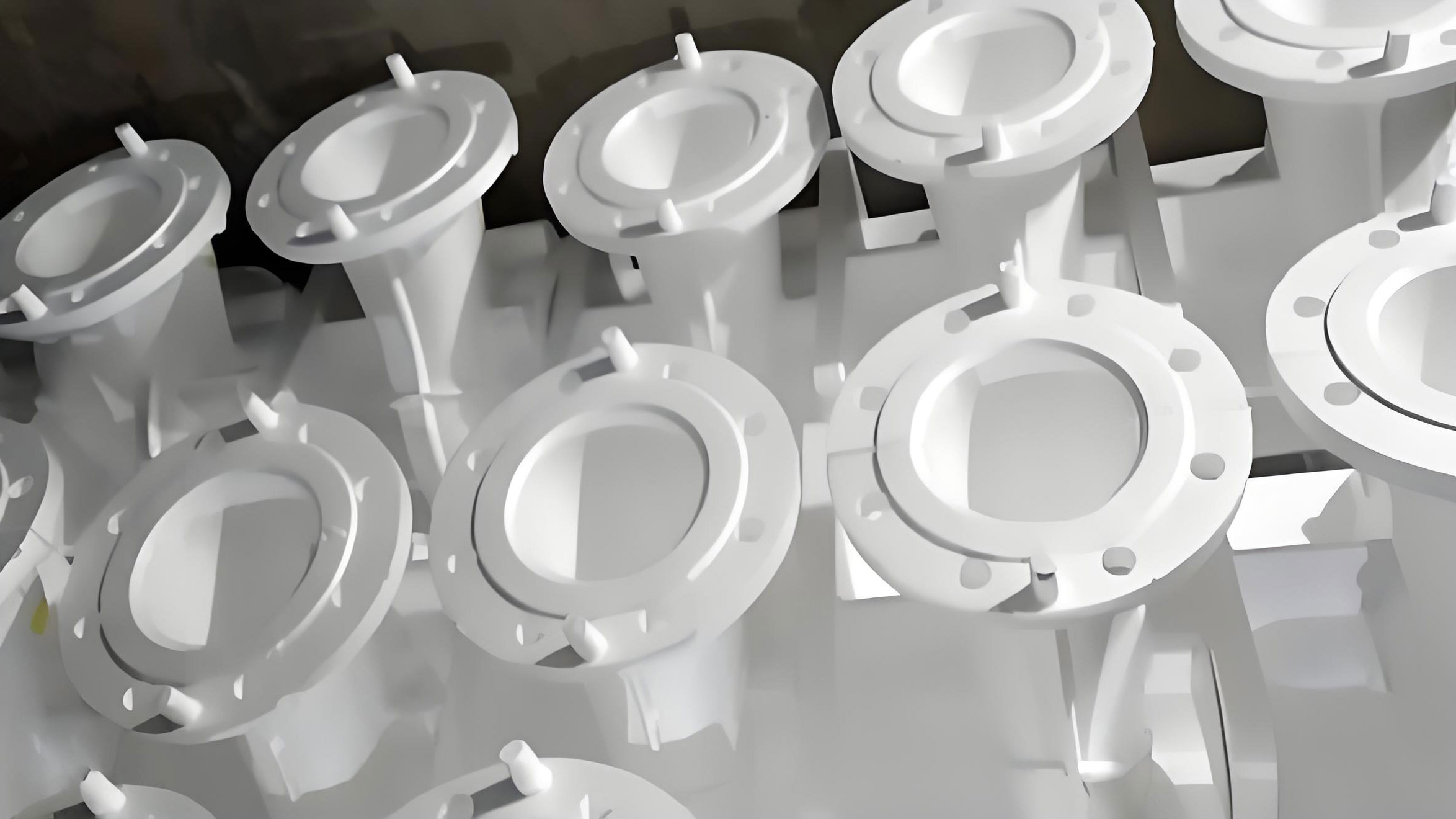
ProCAST is a casting simulation software with a high degree of CAD/CAE integration. It can simulate the flow process during metal casting and accurately display the positions of cold shuts, gas entrapment, and oxidized inclusions. I carried out casting filling and solidification simulation analysis on the optimized centrifugal pump process. From the solidification process of the casting, after the molten steel enters the mold cavity, the part near the side wall dissipates heat quickly and begins to solidify first. Then solidification proceeds from the gating system toward the center. At the thick parts such as the inlet and outlet flanges, there are feeding gates. The solidification sequence is consistent with the prediction. The overall mold filling of the casting is stable, and there is no isolated liquid phase region inside. ProCAST can use shrinkage criterion, solidification percentage combined with the Niyama criterion to judge the probability and size of shrinkage porosity in a certain place inside the casting, thereby optimizing the process. The analysis shows that the temperature of the casting part close to the gate is relatively high, and the solidification and filling speed is relatively slow, so defects are likely to form at the end of the solidification stage. From the simulation results, the last solidified part appears in the pouring system. The gate feeding effect is good, and the casting does not form shrinkage cavities or shrinkage porosity defects. This indicates that the pouring system design is reasonable and conforms to the characteristics of the pump case casting pouring and solidification. In a full mold casting simulation, the additional gas generation from the foam pattern would require coupling the foam decomposition and gas pressure with the metal flow, which is a key difference from conventional investment casting simulation.
The Niyama criterion can be written as:
$$N = \frac{G}{\sqrt{R}}$$
where \(G\) is the temperature gradient and \(R\) is the cooling rate. A higher \(N\) value indicates a lower tendency for shrinkage porosity. The cooling rate can be expressed as:
$$R = \frac{dT}{dt}$$
For a casting with a given modulus, the solidification time can be estimated by Chvorinov’s rule:
$$t_s = B \left(\frac{V}{A}\right)^n$$
where \(t_s\) is the solidification time, \(V/A\) is the modulus, \(B\) is a mold constant, and \(n\) is an exponent typically close to 2. The modulus can be written as:
$$M = \frac{V}{A}$$
These relationships were used to check the feeding distance and the riser size in the optimized process. For the full mold casting alternative, the effective mold constant would be different because the foam pattern modifies the heat transfer and gas pressure, but the same modulus concept remains useful for preliminary feeding design in full mold casting.
The optimized casting process was used for trial production of the pump case casting. The pump case casting was subjected to dimensional inspection, RT inspection, microstructure and composition analysis, and mechanical property analysis. For dimensional inspection, the basic dimensions of the casting were checked against the two-dimensional casting drawing. Because the centrifugal pump case has complex curved surface features, traditional manual measurement cannot meet the measurement requirements, and laser scanning was needed for data acquisition and analysis. I used a flexible articulated arm measurement system to collect surface data of the centrifugal pump case. The obtained point cloud data and the original design casting model were imported into Geomagic software for value comparison. The original design model was set as the reference object, and the scanned physical pump case was set as the test object. First, the test data were “fitted” to the original model by best fitting. Then a reasonable color spectrum region was set, with boundary data of \(\pm 6\,mm\) and a best fitting region of \(\pm 0.3\,mm\). The 3D comparison result showed that most of the data inside the pump case were green, light blue, and pale yellow, with no excessively dark areas. This indicates that the physical object is close to the model overall, and the deviation is not large. A section of the pump case interior was selected for data analysis. The internal deviation of the section did not exceed 0.5 mm, which meets the design requirements. Table 5 summarizes the dimensional inspection results. In a full mold casting production line, similar laser scanning would be equally useful because full mold casting can exhibit systematic shrinkage and distortion due to foam pattern deformation.
| Inspection item | Requirement | Measured result | Conclusion |
|---|---|---|---|
| Overall 3D deviation | Within \(\pm 6\,mm\) | Mostly within \(\pm 0.3\,mm\) | Acceptable |
| Section internal deviation | \(\le 0.5\,mm\) | Maximum about 0.413 mm | Acceptable |
| Minimum wall thickness | 3 mm | 3.1 mm | Acceptable |
| Maximum wall thickness | 22 mm | 21.8 mm | Acceptable |
| Inlet flange thickness | 21 mm | 21.2 mm | Acceptable |
| Outlet flange thickness | 19.5 mm | 19.4 mm | Acceptable |
| Surface roughness | \(\le Ra\,12.5\,\mu m\) | \(Ra\,10.8\,\mu m\) | Acceptable |
| Dimensional tolerance | CT7 | CT7 | Acceptable |
For internal RT inspection, the emergency diesel generator water circulation pump case is a key pressure-retaining component of the fluid cavity, and the internal structure of the pump case casting is required to be dense and the flow passage surface smooth. After actual pouring, an X-ray inspection machine was used to perform RT inspection from four positions: forward and side directions. Four groups of images were obtained. The images showed that there were no obvious defects such as pores or impurities inside the pump case. The structural texture was clear, the blackness was uniform, and the outline was distinct. The internal flow passage was smooth, with no cracks or shrinkage porosity. This indicates that the pouring process design is reasonable and has solved the internal defect problem existing in the earlier trial production. Table 6 lists the RT inspection results. In full mold casting, RT inspection is also essential because gas entrapment and incomplete foam decomposition can create internal porosity that may not be visible on the surface.
| RT position | Defect type | Result | Remark |
|---|---|---|---|
| Position 1 | Gas pore, inclusion, crack, shrinkage | None observed | Uniform blackness |
| Position 2 | Gas pore, inclusion, crack, shrinkage | None observed | Clear contour |
| Position 3 | Gas pore, inclusion, crack, shrinkage | None observed | Smooth flow passage |
| Position 4 | Gas pore, inclusion, crack, shrinkage | None observed | No shrinkage porosity |
The pump case casting material is RCCM—2007 austenitic-ferritic stainless steel M3402, also designated Z3NCD19-10M. It is close to national standard 316L in composition but has stricter control of S and P elements. The element composition analysis of the casting sample is shown in Table 7. The chemical composition of the pump case casting meets the specification requirements. RCCM—2007 specifies that the delta ferrite content of M3402 is 12% to 25%. Studies have shown that austenitic stainless steel with a certain ferrite content has higher yield strength, and the presence of ferrite can reduce the occurrence of intergranular corrosion. An inverted metallographic microscope was used to analyze the metallographic structure of the pump case. Because the overall carbon content is not high, the austenitic structure is stable. Combined with the material composition, the chromium and nickel contents are relatively high, and the material has good rust and corrosion resistance. The ferrite content was measured, and the test result showed that the ferrite content was about 13.5%, which meets the requirement. Table 8 summarizes the ferrite content and microstructure evaluation.
| Element | Specified range / wt% | Measured value / wt% | Compliance |
|---|---|---|---|
| C | \(\le 0.04\) | 0.03 | Yes |
| Si | \(\le 1.50\) | 0.91 | Yes |
| Mn | \(\le 1.50\) | 1.13 | Yes |
| P | \(\le 0.03\) | 0.02 | Yes |
| S | \(\le 0.015\) | 0.004 | Yes |
| Cr | 18–21 | 18.5 | Yes |
| Ni | 9–12 | 10.6 | Yes |
| Mo | 2.25–2.75 | 2.28 | Yes |
| Cu | \(\le 1\) | 0.91 | Yes |
| Microstructural feature | Specified requirement | Measured result | Conclusion |
|---|---|---|---|
| Delta ferrite content | 12%–25% | 13.5% | Acceptable |
| Austenite stability | Stable austenitic matrix | Stable | Acceptable |
| Intergranular corrosion resistance | Improved by ferrite | Ferrite present | Acceptable |
| Carbide and sigma phase | Dissolved by solution treatment | Dissolved | Acceptable |
For mechanical property analysis, solution treatment was used. The treatment temperature was 1050 to 1150 °C. Holding at this temperature for a certain time is beneficial for completely dissolving all sigma brittle phases and carbides. According to the testing requirements for M3402 castings in Volume II, Material Section M, of the RCCM—2007 standard, two groups of \(\phi 5\,mm\) tensile specimens and three groups of \(10\,mm \times 10\,mm \times 55\,mm\) impact specimens were machined. The mechanical properties of the casting samples were tested. The test results are shown in Table 9. The measured values of the casting samples meet the performance requirements. At room temperature, the yield strength \(R_{p0.2}\) was 340 MPa, the tensile strength \(R_m\) was 553 MPa, and the elongation \(A\) was 52%. At 350 °C, the yield strength was 175 MPa and the tensile strength was 406 MPa. The room-temperature V-notch impact energy was 160 J, which is well above the minimum average of 80 J. These results confirm that the optimized precision casting process, combined with the selected solution treatment, produces a sound M3402 pump case. I also note that full mold casting would need careful thermal control to achieve similar mechanical properties, because the foam pattern can alter the local cooling rate and may affect ferrite-austenite balance in full mold casting.
| Test item | Test temperature | Property | Specified value | Measured value |
|---|---|---|---|---|
| Tensile | Room temperature | \(R_{p0.2}\) / MPa | \(\ge 210\) | 340 |
| \(R_m\) / MPa | \(\ge 480\) | 553 | ||
| \(A\) / % | \(\ge 35\) | 52 | ||
| Tensile | 350 °C | \(R_{p0.2}\) / MPa | \(\ge 140\) | 175 |
| \(R_m\) / MPa | \(\ge 390\) | 406 | ||
| V-notch impact | Room temperature | Minimum average / J | 80 | 160 |
The optimized process was further evaluated by comparing the initial and optimized process routes. The initial horizontal top plus side pouring system produced a neck shrinkage porosity defect. The optimized vertical pouring system with enlarged risers moved the hot spot into the gating system and provided sufficient feeding to the thick flanges and neck. The simulation results showed that the last solidified region was in the pouring system, and the casting had no isolated liquid regions. The RT inspection confirmed that there were no internal defects after optimization. The dimensional inspection confirmed that the casting dimensions were within the required tolerance. The chemical composition and mechanical properties met the RCCM—2007 requirements. The ferrite content was about 13.5%, which is within the specified range of 12% to 25%. These results demonstrate that the optimized precision casting process is feasible and reliable for the emergency diesel generator electric pump case.
Table 10 compares the initial and optimized process in terms of defect risk and quality. Table 11 compares full mold casting and investment casting for this pump case, because full mold casting was considered as an alternative route. Although full mold casting can offer advantages such as no draft requirement, fewer parting lines, and potentially lower tooling cost, it also introduces foam pattern decomposition, gas evolution, carbon pickup risk, and different shrinkage behavior. For a nuclear-grade M3402 pump case with strict S and P control and high reliability requirements, the investment casting route was selected, but the full mold casting comparison helped identify the importance of venting, gating, and thermal control. In particular, the full mold casting route would require a gating system designed to manage foam gas and to avoid gas entrapment, and the pouring temperature and sand permeability would need to be optimized for full mold casting. The full mold casting benchmark also highlighted that the vertical orientation is beneficial for gas escape, which agrees with the optimized investment casting orientation.
| Process stage | Initial process | Optimized process | Improvement |
|---|---|---|---|
| Pouring orientation | Horizontal | Vertical | Better venting and feeding |
| Gating system | Top + side pouring | Vertical with enlarged risers | Hot spot moved to gating |
| Neck shrinkage | Observed | Not observed | Eliminated |
| RT internal quality | Potential defect risk | No defects | Improved |
| Dimensional accuracy | Acceptable but variable | Within 0.5 mm section deviation | Improved |
| Mechanical properties | Not fully verified | Meets RCCM—2007 | Verified |
| Ferrite content | Not reported | 13.5% | Within 12%–25% |
| Comparison item | Full mold casting | Investment casting |
|---|---|---|
| Pattern material | Foam pattern | Wax pattern |
| Pattern removal | Thermal decomposition during pouring | Dewaxing before pouring |
| Gas evolution | High, from foam decomposition | Low, after dewaxing |
| Draft requirement | Usually not required | Requires pattern withdrawal |
| Parting line | Reduced or eliminated | Present depending on tooling |
| Surface finish | Good but coating dependent | Excellent |
| Dimensional precision | Moderate to good | High |
| Carbon pickup risk | Possible | Low |
| Nuclear code suitability | Needs qualification | Established for this component |
| Application in this work | Benchmark and alternative | Selected production route |
The filling and solidification simulation was also used to estimate the temperature field and the solid fraction evolution. The solid fraction can be expressed as:
$$f_s = \frac{V_s}{V_{total}}$$
where \(V_s\) is the solid volume and \(V_{total}\) is the total volume. The simulation showed that the solid fraction increased smoothly from the mold wall toward the thermal center. At 15% solid fraction, the outer skin had formed, and the inner liquid was still connected. At 35% solid fraction, the mushy zone was still continuous. At 65% solid fraction, the mushy zone began to isolate near the thick sections, but the risers remained liquid. At 85% solid fraction, the last liquid was in the gating system and risers, which confirms effective feeding. This sequence is desirable for a sound casting and is consistent with the Niyama criterion prediction.
The pouring time can be estimated by:
$$t = K \sqrt{W}$$
where \(t\) is the pouring time, \(W\) is the casting weight, and \(K\) is a coefficient depending on the alloy and casting complexity. For this pump case, the pouring time was controlled to ensure smooth filling and to avoid turbulence. In full mold casting, the pouring time would need to be extended or otherwise adjusted because the foam decomposition gas must escape through the coating and sand, and excessive pouring speed can cause gas entrapment. Thus, the full mold casting process would require a different pouring time window than the investment casting process.
The Reynolds number for the metal flow in the gating system can be written as:
$$Re = \frac{\rho v D}{\mu}$$
where \(\rho\) is the density, \(v\) is the flow velocity, \(D\) is the hydraulic diameter, and \(\mu\) is the dynamic viscosity. A lower Reynolds number reduces the risk of turbulence and gas entrapment. The gating system was designed to keep the flow relatively smooth. In full mold casting, the gas evolved from the foam pattern can increase the effective back pressure and disturb the flow, so the Reynolds number criterion alone is not sufficient for full mold casting; gas venting and coating permeability must also be considered.
After the optimized process was verified, the final production route was established. The key process parameters are summarized in Table 12. The melting was performed with controlled raw materials and strict S and P control. The shell was made with a silica sol and zircon face layer and silica sol and Shangdian backing layers. The shell was roasted at \((1050 \pm 10)^\circ C\) for at least 1.5 h. The pouring temperature was \((1640 \pm 10)^\circ C\). The solution treatment was \((1090 \pm 10)^\circ C\) for 2 to 2.5 h followed by water quenching. The inspection plan included dimensional laser scanning, RT inspection, chemical composition analysis, metallographic examination, ferrite content measurement, and mechanical property testing. All results met the RCCM—2007 requirements for M3402 castings.
| Process step | Parameter | Value |
|---|---|---|
| Melting | Furnace type | Medium-frequency induction furnace |
| Melting | Raw material | 316L scrap and returned material with \(S \le 0.015\%\), \(P \le 0.030\%\) |
| Shell making | Face layer | Silica sol + zircon powder/sand |
| Shell making | Backing layers | Silica sol + Shangdian sand/powder |
| Shell making | Total layers | 10.5 |
| Shell roasting | Temperature | \((1050 \pm 10)^\circ C\) |
| Shell roasting | Holding time | \(\ge 1.5\,h\) |
| Pouring | Pouring temperature | \((1640 \pm 10)^\circ C\) |
| Solution treatment | Temperature | \((1090 \pm 10)^\circ C\) |
| Solution treatment | Holding time | 2–2.5 h |
| Solution treatment | Cooling | Water quenching |
| Inspection | Dimensional | Laser scanning and Geomagic comparison |
| Inspection | Internal | RT from four positions |
| Inspection | Chemical | Element analysis |
| Inspection | Metallographic | Microstructure and ferrite content |
| Inspection | Mechanical | Tensile and impact testing |
The final conclusion of this work is that the precision casting process for the M3402 austenitic-ferritic stainless steel pump case of the emergency diesel generator electric pump was successfully developed. The initial horizontal top plus side pouring system caused shrinkage porosity at the neck outlet. By changing the pouring system from horizontal top plus side pouring to a vertical pouring system, and by enlarging risers in the thick sections, the problems of incomplete filling and uneven heat dissipation in thick parts were solved, and the neck shrinkage porosity defect was effectively prevented. The ProCAST software was used to simulate the solidification process of the pump case, predict the defect positions, and assist the process design. The process verification test produced an M3402 austenitic-ferritic stainless steel pump case with a ferrite content of about 13.5%. The outline dimensions met the precision requirements, and the chemical composition and mechanical properties met the testing requirements for M3402 castings in Volume II, Material Section M, of RCCM—2007. The results also show that full mold casting can be considered as a comparative route for similar pump cases, but for nuclear-grade M3402 with strict composition and reliability requirements, the investment casting route with full mold casting benchmarking provided a robust path to qualified production. The full mold casting concept remains valuable for future work on larger pump cases or less critical water circulation components, where the advantages of full mold casting in reducing parting lines and draft requirements may be exploited, provided that gas evolution and carbon pickup are controlled.
In summary, I established a repeatable precision casting route for the emergency diesel generator electric pump case. The route includes controlled melting, wax pattern manufacturing, shell making, shell roasting, gravity pouring, solution treatment, and comprehensive inspection. The optimized gating system and the vertical orientation were the most important changes. The simulation and experimental results were consistent. The casting dimensions were accurate, the internal quality was sound, the microstructure contained the required ferrite content, and the mechanical properties exceeded the minimum requirements. This work provides a practical reference for manufacturing similar nuclear-grade stainless steel pump cases and for evaluating full mold casting as an alternative forming method. The repeated use of full mold casting comparisons in this study helped clarify the critical role of venting, gating, and thermal management in any casting route for complex thin-walled pump cases. The final production route is therefore recommended for the M3402 pump case, with full mold casting retained as a possible future option after dedicated qualification for gas evolution and carbon control.