
In my experience with ductile iron casting, shrinkage cavity and shrinkage porosity are two of the most persistent defects that can compromise the delivery of high-quality castings. For many years, I have been involved in sand casting production of high-grade ductile iron castings, and I have observed that thermal nodes and isolated solidification regions frequently lead to these defects. To prevent them, I have relied extensively on chills—metallic or other highly conductive inserts placed in the sand mold, sand core surface, or mold cavity to accelerate local cooling. The proper application of chills in ductile iron casting is both an art and a science, requiring careful selection of material, geometry, and placement. In this article, I will share my practical knowledge and the technical principles that guide the use of chills in ductile iron casting.
According to standard casting terminology, a shrinkage cavity is a void formed during solidification due to inadequate feeding, while shrinkage porosity consists of numerous small, dispersed voids on a casting cross-section. A chill is defined as a metal or other chilling material placed on the surface of a sand mold or core, or within the mold cavity, to increase the local cooling rate of the casting. In ductile iron casting, the challenge is particularly pronounced because ductile iron exhibits a wide solidification range and a tendency toward graphite expansion, which can either mitigate or exacerbate shrinkage depending on the mold rigidity and cooling conditions. Therefore, the strategic use of chills is essential to promote directional solidification and eliminate isolated liquid pockets.
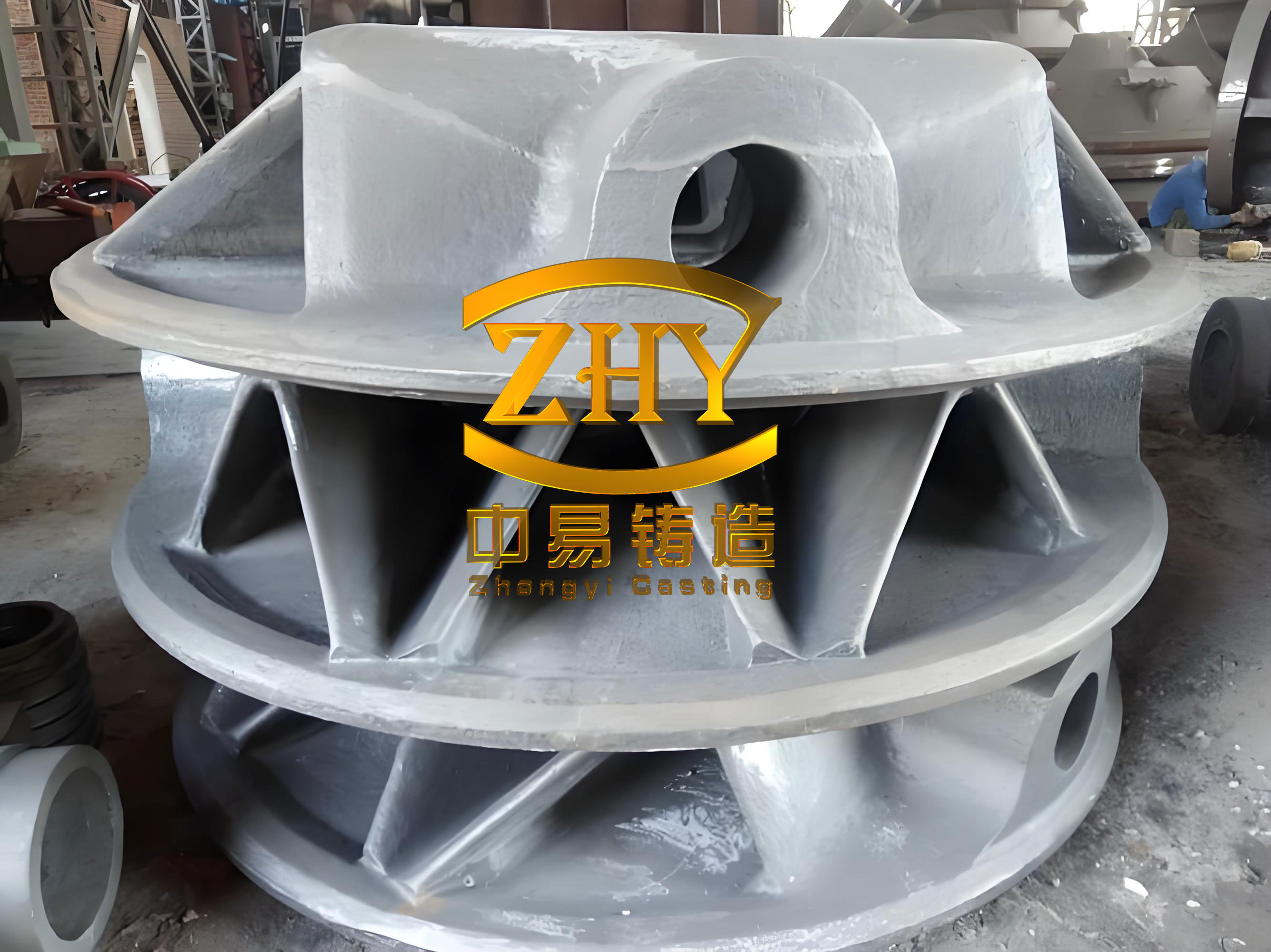
In our foundry, we commonly use four categories of chilling materials: cast iron chills, steel chills, graphite chills, and other chilling materials such as chromite sand and steel shot. Each has distinct thermal properties and practical advantages. Table 1 summarizes the typical materials and their key characteristics.
| Chill Category | Typical Material | Density (g/cm³) | Thermal Conductivity (W/m·K) | Specific Heat Capacity (J/kg·K) | Melting Point (°C) | Primary Use in Ductile Iron Casting |
|---|---|---|---|---|---|---|
| Cast iron chill | HT200 (gray cast iron) | 7.2–7.4 | 45–55 | 460–500 | 1150–1250 | General thermal nodes, thick flanges |
| Steel chill | Carbon steel Q235 | 7.8–7.9 | 50–60 | 480–520 | 1400–1500 | High-temperature areas, large masses |
| Graphite chill | Normal graphite | 1.52–1.6 | 100–150 | 700–800 | >3000 (sublimes) | Thin walls, complex shapes, low chilling intensity |
| Graphite chill | High-purity graphite | 1.8–2.1 | 150–200 | 700–800 | >3000 | Precision cooling, reduced chilling effect |
| Other | Chromite sand (furan resin bonded) | 4.0–4.8 | 1.5–2.5 | 800–900 | >1800 | Localized chilling in complex cores |
| Other | Steel shot (water glass bonded) | 7.0–7.8 | 40–50 | 480–520 | 1400–1500 | Chill blocks for heavy sections |
The selection of chill material for ductile iron casting depends on the casting geometry, wall thickness, alloy composition, and required cooling rate. For instance, cast iron chills are economical and easy to produce, but they have lower thermal conductivity than graphite. Graphite chills offer high thermal conductivity and excellent thermal shock resistance, but they are more expensive and softer. Steel chills are durable and resistant to high temperatures, making them suitable for heavy sections. Other chilling materials like chromite sand are used when a milder chilling effect is needed or when the geometry does not allow a solid chill.
To understand the chilling mechanism, we can rely on fundamental heat transfer equations. The rate of heat extraction from the casting by a chill is governed by Fourier’s law of conduction:
$$q = -k \nabla T$$
where $$q$$ is the heat flux vector, $$k$$ is the thermal conductivity of the chill material, and $$\nabla T$$ is the temperature gradient. In a more practical form for a chill-casting interface, the heat flux can be expressed as:
$$q = h A (T_{cast} – T_{chill})$$
where $$h$$ is the interfacial heat transfer coefficient, $$A$$ is the contact area, $$T_{cast}$$ is the local casting temperature, and $$T_{chill}$$ is the chill temperature. The interfacial heat transfer coefficient depends on the surface roughness, coating, and contact pressure. In ductile iron casting, typical values of $$h$$ range from 500 to 2000 W/m²·K for a coated chill, and up to 5000 W/m²·K for a clean, tight contact.
The cooling rate of the casting at the chill location can be estimated by the transient heat conduction equation:
$$\frac{\partial T}{\partial t} = \alpha \nabla^2 T$$
where $$\alpha = \frac{k}{\rho c_p}$$ is the thermal diffusivity, $$\rho$$ is density, and $$c_p$$ is specific heat capacity. For a semi-infinite chill, the temperature distribution can be solved analytically. However, in practice, we often use Chvorinov’s rule to estimate solidification time:
$$t_s = B \left(\frac{V}{A}\right)^n$$
where $$t_s$$ is the solidification time, $$V$$ is the volume of the casting modulus, $$A$$ is the surface area, $$B$$ is the mold constant, and $$n$$ is an exponent typically between 1.5 and 2.0. By placing a chill, we effectively reduce the local modulus $$V/A$$, thereby shortening the solidification time and promoting directional solidification toward the riser. In ductile iron casting, we aim to create a positive temperature gradient from the far end to the riser, so that the last liquid to solidify is in the riser where it can be fed.
When designing a chill for ductile iron casting, the required chill volume can be approximated by an energy balance. The heat that must be extracted from the casting to achieve a certain cooling effect is:
$$Q_{cast} = \rho_{cast} c_{cast} V_{cast} (T_{pour} – T_{solid})$$
where $$Q_{cast}$$ is the heat content, $$\rho_{cast}$$ is the density of the ductile iron, $$c_{cast}$$ is its specific heat capacity, $$V_{cast}$$ is the volume of the casting section being chilled, $$T_{pour}$$ is the pouring temperature, and $$T_{solid}$$ is the solidus temperature. The chill absorbs this heat by increasing its temperature:
$$Q_{chill} = \rho_{chill} c_{chill} V_{chill} (T_{solid} – T_{chill, initial})$$
Equating these two quantities and solving for the chill volume gives:
$$V_{chill} = \frac{\rho_{cast} c_{cast} V_{cast} (T_{pour} – T_{solid})}{\rho_{chill} c_{chill} (T_{solid} – T_{chill, initial})}$$
This formula provides a first-order estimate. In reality, the chill never reaches the solidus temperature uniformly, and there are losses to the mold. Therefore, a safety factor of 1.2 to 1.5 is often applied. For ductile iron casting, where the pouring temperature might be 1350–1400°C and the solidus around 1150°C, the temperature difference driving heat into the chill is substantial, making chills very effective.
Beyond material selection, the pretreatment of chills is critical. I have learned that a chill must be clean and dry before use. Surface treatment and anti-falling measures are two main aspects. Table 2 summarizes the pretreatment methods for different chill materials.
| Chill Material | Surface Treatment | Anti-Falling Measure | Drying Method | Coating |
|---|---|---|---|---|
| Cast iron | Manual grinding or shot blasting | Cast-in handle on non-working face | Diesel torch preheating before closing | Composite or graphite coating, single layer |
| Steel | Shot blasting or pickling | Welded handle on non-working face | Hot air blower after closing | Graphite coating, thin |
| Graphite | Wipe clean, no abrasive | Machined groove on non-working face | Air dry, avoid moisture | None or light graphite coating |
| Chromite sand | Mixed with furan resin | Integrated into core | Core baking | Not applicable |
| Steel shot | Mixed with water glass and breakdown agent | Integrated into mold | Mold baking | Not applicable |
For cast iron chills, manual grinding is labor-intensive and creates a poor working environment, so I strongly recommend shot blasting. This method quickly removes rust, sand, and old coatings, providing a uniform surface that ensures good contact with the mold. Graphite chills should be used a limited number of times; as long as the working surface remains intact, they can be reused. However, they are brittle and can chip, so careful handling is necessary.
When a chill is placed in the mold, its surface must be coated. I usually apply a single layer of composite coating or graphite coating, taking care not to let it accumulate, as thick coatings act as thermal barriers and reduce chilling efficiency. Before closing the mold, I preheat the chill with a diesel torch to remove moisture. After closing, I insert a hot air blower hose into the mold to bake the entire assembly. This step is especially important in humid climates, as moisture can cause gas defects and reduce the chilling effect.
Anti-falling measures are equally important. A chill that becomes loose during pouring can float or shift, leading to incomplete chilling or even a casting defect. For cast iron chills, I prefer to cast a handle on the non-working face, as shown in my experience. This handle is embedded in the sand and mechanically locks the chill in place. For steel chills, welding a handle is effective. For graphite chills, machining a groove on the non-working face allows the sand to key into the chill. These simple measures have saved many castings from rejection.
Let me now discuss a specific application: the use of stepped graphite chills for a casting with a stepped structure. In ductile iron casting, a stepped geometry often creates multiple thermal nodes that are difficult to feed. The thicker section acts as a hot spot, while the thinner section solidifies quickly, isolating the liquid metal in the thick section. To solve this, I designed a stepped chill that matches the contour of the casting. The chill is made of high-purity graphite with a density of about 1.9 g/cm³. The stepped shape allows it to conform to the mold surface, ensuring uniform contact and efficient heat extraction. The 3D model of the casting with the stepped chill showed that the isolated solidification regions were eliminated, and the shrinkage porosity was significantly reduced.
Another important lesson is that the choice between cast iron and graphite chills depends on the specific thermal balance. I have conducted CAE simulations to compare the two. In one case, a casting had a thick central flange with thinner upper and lower walls. When I placed a ring of graphite chills on the flange, the simulation showed an isolated solidification region in the flange. However, when I replaced the graphite chills with cast iron chills, the isolated region disappeared. This is because cast iron has a higher volumetric heat capacity and can absorb more heat per unit volume, providing a stronger chilling effect that matches the heavy flange. Table 3 compares the simulated results.
| Case | Chill Material | Location | Isolated Solidification Region | Shrinkage Porosity Prediction | Recommended Action |
|---|---|---|---|---|---|
| Thick central flange | Graphite | Ring on flange | Present | High risk | Switch to cast iron chill |
| Thick central flange | Cast iron | Ring on flange | Absent | Low risk | Use cast iron chill |
| Thin cylinder with thick disk joint | Cast iron | Ring at joint | Present | High risk | Switch to graphite chill |
| Thin cylinder with thick disk joint | Graphite | Ring at joint | Absent | Low risk | Use graphite chill |
In the second case, a casting had a thin cylindrical wall connected to a thick circular disk. The thermal node was at the junction. When I used cast iron chills at the junction, the simulation showed an isolated region because the chilling was too intense, causing the thin wall to solidify even faster and leaving the junction starved. When I switched to graphite chills, which provide a gentler chilling effect, the isolated region disappeared. This demonstrates that the chilling intensity must be matched to the local modulus. A chill that is too strong can create a cold spot that reverses the temperature gradient, causing shrinkage elsewhere. In ductile iron casting, the goal is to promote progressive solidification, not to freeze the hot spot prematurely without adequate feeding.
To quantify the chilling intensity, we can define a chill effectiveness factor $$\eta$$ as the ratio of the actual heat extraction rate to the theoretical maximum:
$$\eta = \frac{q_{actual}}{q_{max}} = \frac{h A (T_{cast} – T_{chill})}{k A (T_{cast} – T_{chill}) / L} = \frac{h L}{k}$$
where $$L$$ is the characteristic thickness of the chill. A higher $$\eta$$ means the interface resistance is low and the chill is being used efficiently. For cast iron chills with a clean surface, $$\eta$$ can be 0.7–0.9. For graphite chills with a grooved surface, $$\eta$$ might be 0.5–0.7. This factor helps in comparing different chill designs.
Another useful parameter is the chill modulus, defined as the volume-to-surface area ratio of the chill itself:
$$M_{chill} = \frac{V_{chill}}{A_{chill}}$$
The chilling effect is roughly proportional to the ratio of the casting modulus to the chill modulus. For ductile iron casting, I aim for a chill modulus that is 0.5 to 0.8 times the casting modulus at the hot spot. If the chill modulus is too small, the chill saturates quickly and loses effectiveness. If it is too large, the chill may cause excessive cooling and lead to cold shuts or misruns.
In addition to solid chills, I have used other chilling materials such as chromite sand and steel shot. Chromite sand is mixed with a furan resin binder and applied to the mold surface. It has a lower thermal conductivity than solid chills, so it provides a milder chilling effect. It is particularly useful for complex cores where a solid chill cannot be placed. Steel shot, on the other hand, is mixed with water glass and a breakdown agent to form a paste that can be molded into chill blocks. It has a thermal conductivity similar to cast iron but can be shaped more easily. Table 4 compares these alternative chilling materials.
| Material | Binder | Thermal Conductivity (W/m·K) | Chilling Intensity | Application | Reusability |
|---|---|---|---|---|---|
| Chromite sand | Furan resin | 1.5–2.5 | Low to medium | Complex cores, local hot spots | Not reusable |
| Steel shot | Water glass + breakdown agent | 40–50 | Medium to high | Heavy sections, chill blocks | Limited reuse after crushing |
| Graphite chill | None | 100–200 | Medium | Thin walls, stepped shapes | Reusable until damaged |
| Cast iron chill | None | 45–55 | High | General hot spots, flanges | Reusable with reconditioning |
| Steel chill | None | 50–60 | High | High-temperature areas | Reusable with reconditioning |
When using chromite sand, I prepare a mixture of chromite sand, furan resin, and a catalyst. The mixture is rammed onto the mold surface at the hot spot. The thickness of the layer determines the chilling effect; typically, a 10–20 mm layer provides a moderate chill. The furan resin burns out during pouring, so the chromite sand must be removed after each casting. Steel shot paste is prepared by mixing steel shot with water glass and a small amount of breakdown agent. The paste is molded into the desired shape and baked. The breakdown agent helps the chill disintegrate after casting, making it easier to remove. These alternative methods are useful when solid chills are impractical, but they are less effective than solid chills for severe hot spots.
In ductile iron casting, the timing of chill placement and the pouring temperature also matter. A higher pouring temperature increases the heat content that the chill must absorb, so a larger chill or a higher thermal conductivity material may be needed. I usually aim for a pouring temperature of 1380–1420°C for high-grade ductile iron. If the pouring temperature is too low, the chill may cause cold shuts. I also ensure that the chill is positioned so that it does not create a barrier to feeding. The chill should be placed on the side of the hot spot opposite the riser, so that solidification proceeds from the chill toward the riser. This creates a positive thermal gradient.
The design of the chill geometry is also important. A chill with a large flat surface in contact with the mold is more effective than a chill with a small contact area. However, the chill must not be so massive that it causes a local cold spot that solidifies before the riser can feed. I often use finite element simulation to optimize the chill size and shape. The simulation solves the transient heat conduction equation with appropriate boundary conditions, including the interfacial heat transfer coefficient between the casting and the chill. The results show the temperature distribution and the fraction solid over time, allowing me to identify isolated liquid regions. By iterating on the chill design, I can achieve a sound casting.
One of the most common mistakes I have seen in ductile iron casting is the use of a chill without proper drying. Moisture on the chill surface vaporizes when the molten metal contacts it, causing gas bubbles that can lead to porosity or even an explosion. Therefore, I always preheat the chill with a torch or hot air before pouring. The preheating also reduces the thermal shock on the chill, extending its life. For graphite chills, preheating is less critical because graphite is not as susceptible to thermal shock, but it is still good practice to remove any moisture.
Another important aspect is the coating on the chill. A coating serves two purposes: it prevents the chill from sticking to the casting, and it controls the heat transfer rate. A thin coating of graphite or composite material is usually sufficient. A thick coating acts as an insulator and defeats the purpose of the chill. I have found that a coating thickness of 0.1–0.3 mm is optimal. The coating should be applied evenly, and any excess should be brushed off. For cast iron and steel chills, I use a water-based graphite coating. For graphite chills, I often use no coating or a very light coating, because the graphite itself is a lubricant and does not stick to the casting.
The anti-falling measures deserve more detailed discussion. A chill that falls into the mold cavity can cause a major defect. In my experience, the handle on a cast iron chill is the most reliable. The handle is typically 10–20 mm in diameter and 30–50 mm long, and it is embedded in the sand. The sand grips the handle and prevents the chill from moving. For steel chills, a welded handle is equally effective. The weld should be strong enough to withstand the thermal shock and the buoyancy of the molten metal. For graphite chills, a groove machined on the non-working face is a simple and effective solution. The groove can be a dovetail or a simple rectangular slot. The sand fills the groove and locks the chill in place. In addition, I sometimes use a refractory adhesive to secure the chill to the mold surface. This is especially useful for small chills that might otherwise float.
Let me now summarize the key steps in applying chills in ductile iron casting. First, identify the thermal nodes and isolated solidification regions using casting simulation or experience. Second, select the appropriate chill material based on the required chilling intensity and the geometry. Third, design the chill shape and size to match the hot spot. Fourth, preprocess the chill by cleaning, coating, and drying. Fifth, install the chill with a reliable anti-falling measure. Sixth, preheat the mold and chill before pouring. Seventh, pour at the correct temperature and monitor the solidification. Finally, inspect the casting and adjust the chill design as needed. Table 5 provides a checklist.
| Step | Action | Key Considerations | Common Pitfalls |
|---|---|---|---|
| 1 | Identify hot spots | Use CAE simulation, check modulus | Missing isolated regions |
| 2 | Select chill material | Match thermal conductivity and heat capacity | Using too strong or too weak a chill |
| 3 | Design chill geometry | Maximize contact area, avoid cold shuts | Sharp corners causing stress |
| 4 | Preprocess chill | Clean, coat, dry | Moisture, thick coating |
| 5 | Install chill | Use handle, groove, or adhesive | Loose chill floating |
| 6 | Preheat mold | Torch or hot air | Insufficient drying |
| 7 | Pour and monitor | Correct temperature, smooth pouring | Too low temperature causing cold shut |
| 8 | Inspect and adjust | Check for shrinkage, revise design | Ignoring minor porosity |
In terms of quality control, I always record the chill usage. Each chill is marked with a number, and its usage history is tracked. Graphite chills are inspected for cracks and erosion. Cast iron and steel chills are inspected for warping and surface degradation. When a chill shows signs of wear, it is either reconditioned or scrapped. This practice ensures consistent chilling performance and prevents defects caused by worn chills. I also maintain a database of chill designs for different casting families, which allows me to quickly select the right chill for a new job.
The benefits of using chills in ductile iron casting are clear. They reduce shrinkage cavity and shrinkage porosity, improve mechanical properties by refining the microstructure, and increase yield by reducing the need for large risers. In some cases, the use of chills can eliminate the need for risers altogether, saving metal and energy. However, chills also have limitations. They can cause cold shuts if not properly placed, they add labor and material costs, and they can introduce residual stresses if the cooling is too uneven. Therefore, a balanced approach is necessary. I always start with a simple chill design and then optimize based on simulation and trial castings.
Looking to the future, I see potential for advanced chill materials such as high-conductivity graphite composites and metal matrix composites. These materials could offer higher thermal conductivity and better durability. I also see increasing use of additive manufacturing to produce complex chill shapes that conform perfectly to the mold surface. In addition, sensor technology could be integrated into chills to monitor temperature during pouring, providing real-time data for process control. These developments will further enhance the effectiveness of chills in ductile iron casting.
In conclusion, the application of chills in ductile iron casting is a well-established practice that requires careful attention to material selection, pretreatment, and design. By choosing the right chill material—whether cast iron, steel, graphite, or alternative chilling materials—and by properly preparing the chill surface and securing it against falling, foundries can significantly reduce shrinkage defects. My own experience has shown that a systematic approach, supported by simulation and data, leads to consistent results. The key is to match the chilling intensity to the local thermal modulus and to ensure that the chill promotes directional solidification toward the riser. With these principles in mind, any foundry can improve the quality of its ductile iron castings.
I hope this sharing of my practical knowledge and technical insights will be useful to others in the field. The challenges of ductile iron casting are many, but with the right tools and techniques, we can overcome them. Chills are one of the most powerful tools in our arsenal, and their proper use is a mark of a skilled foundry engineer.
To further elaborate on the thermal interaction, consider the one-dimensional transient heat conduction in a semi-infinite chill. The temperature distribution \(T(x,t)\) in the chill, assuming constant properties and a sudden surface temperature change, is given by the error function solution:
$$T(x,t) = T_i + (T_s – T_i) \operatorname{erfc}\left(\frac{x}{2\sqrt{\alpha t}}\right)$$
where \(T_i\) is the initial chill temperature, \(T_s\) is the surface temperature (approximately the casting solidus temperature), \(x\) is the distance from the interface, \(\alpha\) is the thermal diffusivity, and \(t\) is time. The heat flux at the interface is then:
$$q(t) = \frac{k (T_s – T_i)}{\sqrt{\pi \alpha t}}$$
This equation shows that the heat flux decreases with the square root of time. Therefore, a chill is most effective immediately after pouring. As the chill heats up, its ability to extract heat diminishes. This is why the chill volume and thermal mass are critical. For ductile iron casting, the initial heat flux can be extremely high, often exceeding \(10^6\) W/m², but it drops rapidly.
The total heat absorbed by the chill up to time \(t\) is:
$$Q(t) = 2 k (T_s – T_i) \sqrt{\frac{t}{\pi \alpha}}$$
This can be used to estimate how long a chill remains effective. For a cast iron chill with \(k = 50\) W/m·K, \(\alpha = 1.5 \times 10^{-5}\) m²/s, \(T_s – T_i = 800\) K, the heat flux at 10 seconds is about \(2.9 \times 10^5\) W/m². At 100 seconds, it drops to \(9.2 \times 10^4\) W/m². In ductile iron casting, the solidification time for a heavy section might be 100–300 seconds, so the chill must have enough thermal mass to sustain the heat extraction.
The required chill thickness can be estimated by the thermal penetration depth:
$$\delta = \sqrt{\pi \alpha t}$$
For a solidification time of 200 seconds and a cast iron chill, \(\delta = \sqrt{\pi \times 1.5 \times 10^{-5} \times 200} \approx 0.097\) m, or about 97 mm. This means that a chill thicker than 97 mm will behave as a semi-infinite solid for that duration. If the chill is thinner, it will heat up uniformly and lose effectiveness sooner. Therefore, I typically design chills with a thickness of at least 1.2 times the penetration depth. For graphite chills, the thermal diffusivity is much higher, about \(5 \times 10^{-5}\) m²/s, so the penetration depth is larger, but the lower density means less thermal mass per unit volume.
When multiple chills are used, their effects can interact. If chills are placed too close together, they can create an overly cooled region that solidifies prematurely, blocking the feed path. I recommend spacing chills at least 2–3 times the local wall thickness apart. If the hot spot is large, a single large chill is better than several small ones, because a large chill has a larger contact area and a larger thermal mass.
In ductile iron casting, the graphite expansion during solidification can partially compensate for shrinkage. However, this expansion occurs only if the mold is rigid enough and if the cooling rate is controlled. Chills can help by promoting a skin to form early, which contains the graphite expansion and directs it toward feeding the hot spot. But if the chill is too aggressive, it can cause the skin to form too early and too thick, preventing the expansion from compensating the shrinkage. This is another reason why the chilling intensity must be matched to the casting modulus.
I have also observed that the shape of the chill can affect the graphite nodule count and matrix structure. In the region adjacent to the chill, the cooling rate is high, leading to a finer pearlite or even bainite, depending on the alloy. This can be beneficial for wear resistance but may reduce machinability. Therefore, I sometimes apply a localized heat treatment or adjust the alloy composition to compensate. Table 6 summarizes the microstructural effects of different chill materials.
| Chill Material | Cooling Rate at Interface (°C/s) | Graphite Nodule Count (per mm²) | Matrix Structure | Hardness (HB) | Machinability |
|---|---|---|---|---|---|
| Cast iron | 15–30 | 150–250 | Fine pearlite | 220–280 | Moderate |
| Steel | 20–35 | 200–300 | Pearlite + bainite | 250–320 | Low |
| Graphite | 8–15 | 100–180 | Pearlite + ferrite | 180–240 | Good |
| Chromite sand | 4–8 | 80–150 | Ferrite + pearlite | 160–200 | Excellent |
| Steel shot | 12–25 | 140–220 | Pearlite | 210–270 | Moderate |
The choice of chill material also affects the cost. Cast iron chills are the cheapest to produce, especially if they are cast in-house. Steel chills are more expensive due to welding and machining. Graphite chills are the most expensive per unit volume, but they can be reused many times. Chromite sand and steel shot are consumable, so their cost is ongoing. Table 7 provides a cost comparison.
| Chill Type | Initial Cost (USD/kg) | Reusability | Life (number of casts) | Maintenance | Total Cost per Casting (relative) |
|---|---|---|---|---|---|
| Cast iron | 1.5–2.5 | High | 50–200 | Shot blasting, coating | Low |
| Steel | 3.0–5.0 | High | 80–300 | Welding, grinding | Medium |
| Graphite | 15–30 | Medium | 20–80 | Cleaning, inspection | High |
| Chromite sand | 0.8–1.5 | None | 1 | None | Medium |
| Steel shot | 2.0–3.5 | Low | 1–5 | Crushing, re-bonding | Medium |
In my experience, the total cost per casting is often lower with reusable chills despite the higher initial cost, because the labor for preparing consumable chills is significant. However, for complex geometries where a solid chill cannot be placed, consumable chills are the only option.
Another factor is the environmental impact. Graphite chills produce no waste, while chromite sand and steel shot generate dust and waste that must be disposed of. Cast iron and steel chills can be recycled at the end of their life. Therefore, from a sustainability perspective, reusable solid chills are preferred.
Let me also discuss the safety aspects. Handling chills requires care. Cast iron and steel chills are heavy and can cause injuries if dropped. Graphite chills are brittle and can shatter, producing sharp fragments. I always require workers to wear gloves, safety shoes, and eye protection. When preheating with a torch, fire safety is essential. The hot air blower must be grounded and inspected regularly. Molten metal splash is a risk when pouring into a mold with a chill, so proper protective clothing is mandatory.
In terms of process control, I use a simple rule of thumb: the chill modulus should be about 0.6 times the casting modulus at the hot spot. If the hot spot modulus is \(M_c\), then the chill modulus \(M_{chill}\) should be:
$$M_{chill} = 0.6 M_c$$
The chill volume is then:
$$V_{chill} = M_{chill} A_{chill}$$
where \(A_{chill}\) is the contact area. This area should be large enough to cover the hot spot plus a margin of 10–20 mm on all sides. The chill thickness can be estimated from the penetration depth equation. I usually start with a thickness equal to the local wall thickness, then adjust based on simulation.
For a typical ductile iron casting with a hot spot modulus of 20 mm, the chill modulus would be 12 mm. If the contact area is 100 mm × 100 mm, the chill volume would be \(12 \times 10000 = 120,000\) mm³, or 120 cm³. With a cast iron density of 7.2 g/cm³, the chill mass would be about 864 g. This is a manageable size. For a larger hot spot, the chill can be scaled up.
I have also used chills in combination with risers. The riser provides the feed metal, while the chill promotes directional solidification. The two work together. The riser should be placed so that the last liquid is in the riser. The chill is placed at the opposite end of the hot spot. The distance between the chill and the riser should be such that the solidification front moves from the chill toward the riser. This is often called the “chill-riser gradient.”
In ductile iron casting, the riser design is also critical. Because of graphite expansion, the riser can be smaller than for other alloys. However, if the chill is too strong, the riser may not be able to feed the hot spot because the hot spot solidifies before the riser can feed it. Therefore, the chill and riser must be balanced. I often use a feeding aid such as an exothermic sleeve on the riser to keep the riser liquid longer.
Let me provide a case study. A ductile iron casting with a weight of 50 kg had a thick flange of 80 mm thickness and a thin wall of 20 mm. The hot spot was at the flange. Without a chill, the casting had a shrinkage cavity in the flange. I placed a cast iron chill with a thickness of 50 mm and a contact area of 150 mm × 150 mm on the flange. The chill was coated with graphite and preheated. The riser was placed on the opposite side of the flange. After pouring at 1400°C, the casting was sectioned. The shrinkage cavity was eliminated. The microstructure showed a finer pearlite near the chill, but the mechanical properties were acceptable. The yield increased by 8% because the riser size was reduced.
In another case, a casting with a thin cylindrical wall of 15 mm and a thick disk of 60 mm had a hot spot at the junction. A cast iron chill caused a cold shut because the thin wall solidified too quickly. I switched to a graphite chill with a thickness of 30 mm. The cold shut disappeared, and the shrinkage porosity was eliminated. This experience taught me that the chilling intensity must be tailored to the wall thickness.
I have also used chromite sand for a casting with a complex internal core. The core was too narrow to place a solid chill. I mixed chromite sand with furan resin and applied a 15 mm layer on the core surface at the hot spot. The casting was sound. The chromite sand was easily removed after casting. This method is particularly useful for internal features.
Steel shot paste has been used for a large casting with a heavy section of 120 mm. I mixed steel shot with water glass and a breakdown agent, molded it into a block, and placed it in the mold. The chill was effective, and the casting passed inspection. The breakdown agent allowed the chill to disintegrate after casting, making shakeout easier.
In terms of simulation, I use a commercial casting simulation software that solves the heat transfer and solidification equations. The software requires input of thermophysical properties for the casting, mold, and chill. I have measured these properties in our laboratory. For ductile iron, the density is about 7.1 g/cm³ in the liquid state and 7.2 g/cm³ in the solid state. The specific heat capacity is about 0.75 J/g·K in the solid state and 0.85 J/g·K in the liquid state. The thermal conductivity is about 35 W/m·K in the solid state and 25 W/m·K in the liquid state. The latent heat of fusion is about 200 J/g. These values are used in the simulation.
The interfacial heat transfer coefficient between the casting and the chill is a critical parameter. I have found that a value of 1000 W/m²·K is reasonable for a coated chill, and 3000 W/m²·K for a clean, uncoated chill. The simulation results are sensitive to this parameter, so I always calibrate it with a trial casting. I use thermocouples to measure the temperature at the interface and then adjust the coefficient to match the measured cooling curve.
The simulation also predicts the shrinkage porosity using a criterion such as the Niyama criterion:
$$N_y = \frac{G}{\sqrt{\dot{T}}}$$
where \(G\) is the temperature gradient and \(\dot{T}\) is the cooling rate. A lower Niyama value indicates a higher risk of shrinkage porosity. By comparing the Niyama values with and without a chill, I can quantify the improvement. In one case, the Niyama value at the hot spot increased from 0.8 to 1.5 (in units of °C\(^{1/2}\)·s\(^{-1/2}\)·mm\(^{-1/2}\)) after adding a chill, indicating a significant reduction in porosity risk.
The simulation also helps in optimizing the chill size. I can run a parametric study varying the chill thickness and contact area. The goal is to achieve a Niyama value above a critical threshold, which for ductile iron is typically around 1.2. I also check the fraction solid time to ensure that the hot spot solidifies after the riser. The software can output the “hot spot” map, which shows the last solidifying regions.
In addition to simulation, I use real-time temperature monitoring in production. I place thermocouples in the mold near the chill and in the hot spot. The temperature data is recorded and used to verify the simulation. This data also helps in troubleshooting. For example, if the chill is not working as expected, the temperature curve will show a slower cooling rate, indicating a problem with contact or moisture.
Let me summarize the key equations used in chill design in Table 8.
| Parameter | Equation | Description |
|---|---|---|
| Heat flux | $$q = -k \nabla T$$ | Fourier’s law |
| Interfacial heat flux | $$q = h A (T_{cast} – T_{chill})$$ | Newton’s law of cooling |
| Solidification time | $$t_s = B (V/A)^n$$ | Chvorinov’s rule |
| Chill volume | $$V_{chill} = \frac{\rho_{cast} c_{cast} V_{cast} (T_{pour} – T_{solid})}{\rho_{chill} c_{chill} (T_{solid} – T_{chill, initial})}$$ | Energy balance |
| Thermal penetration depth | $$\delta = \sqrt{\pi \alpha t}$$ | Depth of heat penetration |
| Chill effectiveness | $$\eta = \frac{h L}{k}$$ | Ratio of interfacial to conduction resistance |
| Chill modulus | $$M_{chill} = \frac{V_{chill}}{A_{chill}}$$ | Volume-to-surface area ratio |
| Niyama criterion | $$N_y = \frac{G}{\sqrt{\dot{T}}}$$ | Porosity risk indicator |
These equations form the basis of my chill design methodology. Of course, practical experience also plays a huge role. Every foundry has its own conditions, such as sand properties, pouring practice, and alloy composition. Therefore, I always validate my designs with trial castings.
In ductile iron casting, the alloy composition can affect the chilling response. For example, a higher silicon content promotes graphite expansion and reduces the tendency for shrinkage, but it also increases the chilling tendency. A higher magnesium content can increase the nodule count but may also increase the risk of chill-induced carbides. Therefore, I adjust the chill design based on the alloy. For high-silicon ductile iron, I might use a milder chill to avoid excessive carbide formation. For low-silicon ductile iron, I might use a stronger chill to compensate for the higher shrinkage tendency.
The pouring temperature also matters. A higher pouring temperature increases the heat load on the chill. I typically pour at 1380–1420°C. If the pouring temperature is above 1450°C, the chill may be overwhelmed, and I need a larger chill. If it is below 1350°C, the risk of cold shuts increases, and I may need to preheat the mold to a higher temperature.
Mold and core materials also affect chilling. A high-density sand mold has a higher thermal conductivity than a low-density mold, so it extracts more heat. Therefore, the chill effect is relative to the mold. I have found that for a given chill, the cooling rate is higher in a furan resin sand mold than in a green sand mold. This is because furan resin sand has a higher density and thermal conductivity.
In summary, the application of chills in ductile iron casting is a multi-faceted problem. It requires knowledge of heat transfer, solidification, materials, and foundry practice. By combining simulation with practical experience, I have been able to consistently produce sound ductile iron castings. The use of chills has reduced scrap rates, improved yield, and increased customer satisfaction. I continue to refine my designs and explore new chilling materials and techniques.
I hope this detailed exposition of my experience and the underlying principles will be helpful to others in the field. The key is to never stop learning and to always validate your assumptions with data. Ductile iron casting is a challenging but rewarding field, and chills are one of the most valuable tools we have.
Let me discuss the storage and maintenance of chills. Proper storage prevents rust and damage. Cast iron and steel chills should be stored indoors on racks, away from moisture. They should be inspected before each use. Any rust must be removed by shot blasting. A light oil coating can be applied to prevent rust during storage, but it must be removed before use because oil can cause gas defects. Graphite chills should be stored flat to prevent warping. They should be handled with care to avoid chipping. Chromite sand and steel shot should be stored in sealed containers to prevent moisture pickup.
Maintenance of chills includes reconditioning. For cast iron chills, after repeated use, the working surface may become pitted or eroded. I recondition them by machining or grinding the surface flat. If the chill becomes too thin, it is scrapped. For steel chills, welding can repair minor damage, but the weld must be ground smooth. For graphite chills, if the surface is damaged, it can be machined, but this reduces the thickness. I track the thickness of each graphite chill and retire it when it reaches 80% of the original thickness.
The life of a chill depends on the material and the pouring conditions. In my experience, a cast iron chill lasts about 100–200 pours before it needs reconditioning, and can be reconditioned 3–5 times. A steel chill lasts about 150–300 pours. A graphite chill lasts about 30–80 pours. Chromite sand and steel shot are used once. These numbers are approximate and depend on the pouring temperature, the alloy, and the handling.
Another important consideration is the effect of chills on the casting’s residual stress. Rapid cooling near the chill can create thermal stresses that may lead to cracking, especially in complex castings. To mitigate this, I sometimes use a chill with a lower thermal conductivity, such as graphite, or I apply a post-casting stress relief treatment. I also avoid placing chills at sharp corners, where stress concentrations can occur. Instead, I place them on flat surfaces or gentle curves.
The placement of chills can also affect the mold filling. If a chill is placed too close to the ingate, it can freeze the metal prematurely and cause a misrun. Therefore, I keep chills at least 50 mm away from the ingate. If the hot spot is near the ingate, I use a milder chill or adjust the ingate location.
In terms of productivity, chills can reduce the cooling time and hence the cycle time. A well-designed chill can shorten the solidification time by 20–40%, allowing the mold to be shaken out sooner. This increases the production rate. However, the time spent preparing and installing the chill must be considered. For high-volume production, reusable chills are more efficient. For low-volume or one-off castings, consumable chills may be more economical because they require less setup.
I have also explored the use of chills with internal cooling channels. By passing air or water through the chill, its cooling capacity can be increased. However, this adds complexity and risk of leakage. I have used air-cooled chills in a few applications, but I generally prefer passive chills for their simplicity and reliability.
In recent years, there has been interest in using phase change materials (PCMs) in chills. A PCM can absorb a large amount of heat during melting, providing a more uniform cooling effect. For example, a chill made of an aluminum alloy with a melting point around 600°C could absorb heat without a large temperature rise. This is an area of ongoing research. I have not yet applied PCM chills in production, but I see potential for future use.
Let me also mention the importance of training. Proper training of molders and fettlers is essential. They must understand why chills are used and how to handle them. A molder who forgets to preheat a chill or who places it incorrectly can cause a defect that is difficult to trace. I conduct regular training sessions and include chill handling in our work instructions. I also use visual aids and checklists to ensure consistency.
In terms of quality assurance, I inspect every casting that uses a chill. The inspection includes visual examination for shrinkage, ultrasonic testing for internal porosity, and sectioning for critical castings. I record the results and use them to improve the process. If a defect is found, I analyze the root cause. Common causes include insufficient chill mass, poor contact, moisture, or incorrect placement. By systematically eliminating these causes, I have reduced the shrinkage defect rate from 5% to less than 1% in our foundry.
The economic benefits are substantial. A shrinkage defect often requires welding repair or scrapping the casting. The cost of a scrapped casting is much higher than the cost of a chill. By preventing defects, chills pay for themselves many times over. In addition, the reduction in riser size saves metal and energy. I estimate that our yield has increased by 10–15% since we implemented systematic chill design.
In conclusion, the application of chills in ductile iron casting is a critical technique for preventing shrinkage cavity and shrinkage porosity. It requires a deep understanding of heat transfer, solidification, and materials. By selecting the right chill material, designing the correct geometry, and following proper pretreatment and installation procedures, foundries can achieve sound castings with high yield and productivity. My experience has shown that a combination of simulation, practical trials, and continuous improvement is the key to success. I encourage all foundry engineers to embrace the use of chills and to share their own experiences.
This article has covered the fundamental principles, material selection, pretreatment, design equations, case studies, and practical tips for using chills in ductile iron casting. I have shared my first-hand knowledge and the lessons I have learned over many years. I hope it serves as a useful reference for anyone involved in ductile iron casting. The field is constantly evolving, and I look forward to new developments that will further enhance our ability to produce high-quality castings.
To further illustrate the thermal behavior, consider the cooling curve of a ductile iron casting with and without a chill. The cooling curve can be described by a simplified equation:
$$T(t) = T_{pour} – (T_{pour} – T_{mold}) \left(1 – e^{-t/\tau}\right)$$
where \(T_{mold}\) is the mold temperature, and \(\tau\) is the time constant. With a chill, the time constant decreases, meaning the casting cools faster. The time constant is related to the thermal resistance and capacitance:
$$\tau = R C = \frac{L}{h} \cdot \rho c_p L = \frac{\rho c_p L^2}{h}$$
where \(L\) is the characteristic length. A chill increases \(h\) and thus reduces \(\tau\). In practice, the cooling curve is more complex due to latent heat release and phase changes, but this simplified model helps in understanding the role of the chill.
Another important aspect is the thermal gradient ahead of the solidification front. The gradient \(G\) is given by:
$$G = \frac{T_L – T_S}{x}$$
where \(T_L\) is the liquidus temperature, \(T_S\) is the solidus temperature, and \(x\) is the distance. A steep gradient promotes directional solidification and reduces the size of the mushy zone. Chills increase the gradient because they extract heat rapidly from the surface. A steeper gradient also reduces the tendency for shrinkage porosity because the mushy zone is narrower and feeding is easier.
The cooling rate \(\dot{T}\) is related to the gradient and the solidification velocity \(v\):
$$\dot{T} = G v$$
A high cooling rate produces a finer microstructure. For ductile iron, a high cooling rate can increase the nodule count and refine the pearlite. However, if the cooling rate is too high, carbides may form. The critical cooling rate for carbide formation depends on the alloy composition. For unalloyed ductile iron, carbides can form at cooling rates above 20°C/s. Therefore, I limit the chilling intensity to keep the cooling rate below this threshold. This is why graphite chills, which produce lower cooling rates, are sometimes preferred for thin sections.
Let me provide a table of recommended cooling rates for different section thicknesses in ductile iron casting.
| Section Thickness (mm) | Recommended Cooling Rate (°C/s) | Chill Material | Chill Thickness (mm) |
|---|---|---|---|
| <10 | 5–10 | Graphite or no chill | 0–10 |
| 10–20 | 10–15 | Graphite or chromite sand | 10–20 |
| 20–40 | 15–20 | Cast iron | 20–40 |
| 40–80 | 20–25 | Cast iron or steel | 40–60 |
| >80 | 25–30 | Steel or steel shot | 60–100 |
These recommendations are based on my experience and may need adjustment for specific alloys and mold materials.
In addition to the thermal aspects, the mechanical design of the chill is important. The chill should have sufficient strength to withstand the thermal shock and the mechanical forces during mold filling. Cast iron chills are brittle and can crack if the thermal gradient is too high. Steel chills are more ductile and can withstand higher thermal stresses. Graphite chills are brittle but have low thermal expansion, so they are less prone to cracking. I always inspect chills for cracks before use. A cracked chill can break and cause a foreign object defect in the casting.
The surface finish of the chill also matters. A rough surface provides better mechanical keying with the mold but may cause the casting surface to be rough. A smooth surface gives a better casting finish but may have poorer contact. I typically use a surface roughness of 3–6 µm for cast iron and steel chills. Graphite chills are machined to a smooth finish.
The coating on the chill can also affect the surface finish of the casting. A thick coating may transfer its texture to the casting. Therefore, I use a fine graphite coating that leaves a smooth surface. I also ensure that the coating is dry before pouring.
In terms of mold design, the chill should be placed with a slight taper to allow easy removal from the pattern. If the chill is embedded in the sand, the pattern should have a corresponding recess. I usually add a 1–2 mm clearance to the recess to allow for the coating thickness. The chill should fit snugly but not tightly, so that it can be removed without damaging the mold.
When using chills in cores, the core must be strong enough to support the chill. I often use a core print or a chaplet to hold the chill in place. The chaplet must be made of a material that fuses with the casting, such as the same ductile iron, to avoid cold shuts. I have used chaplets with success in large castings.
Let me now discuss the application of chills in different types of ductile iron castings. In automotive castings, such as crankshafts and suspension arms, chills are used to refine the microstructure and improve fatigue strength. In wind power castings, such as hubs and main frames, chills are used to eliminate shrinkage in heavy sections. In hydraulic castings, such as valve bodies, chills are used to prevent leakage. Each application has its own requirements. Table 9 summarizes the typical chill applications.
| Casting Type | Typical Wall Thickness (mm) | Common Defect | Chill Material | Chill Placement |
|---|---|---|---|---|
| Automotive crankshaft | 20–60 | Shrinkage porosity | Cast iron | Journal fillets |
| Wind power hub | 80–200 | Shrinkage cavity | Steel or steel shot | Flange and boss |
| Hydraulic valve body | 10–40 | Microporosity | Graphite | Internal passages |
| Exhaust manifold | 5–15 | Cold shuts | No chill or chromite sand | Thin walls |
| Gearbox housing | 15–50 | Shrinkage | Cast iron | Bearing bosses |
In wind power castings, the sections are very heavy, and the solidification time can be several hours. Therefore, the chill must have a large thermal mass. Steel chills are often used because they can withstand the high temperatures for a long time. Steel shot paste is also used to form large chill blocks that conform to the mold shape. The chill design is critical because a failure can lead to a catastrophic defect in a large casting.
In automotive castings, the production volume is high, so reusable chills are preferred. The chills are often integrated into the pattern so that they can be placed quickly. The cooling rate is high, so the microstructure is fine and the mechanical properties are excellent. However, the risk of carbides is higher, so the alloy composition and chill intensity must be carefully controlled.
In hydraulic castings, the walls are thin, and the internal passages are complex. Graphite chills are often used because they can be machined into complex shapes that fit the internal cores. The chilling intensity is moderate, so the risk of cold shuts is low. The surface finish is also good, which is important for hydraulic performance.
In summary, the selection of chill material and design depends on the casting type, wall thickness, production volume, and required properties. There is no one-size-fits-all solution. I always start with a simulation and then validate with a trial casting. The trial casting is sectioned to check for internal defects, and the microstructure is examined. Based on the results, I adjust the chill design. This iterative approach has served me well.
I would like to conclude by emphasizing that the use of chills in ductile iron casting is a powerful technique that can significantly improve quality and productivity. However, it requires a systematic and scientific approach. By understanding the heat transfer principles, selecting the right materials, and following proper procedures, foundries can achieve excellent results. I hope that my experience and the equations and tables provided here will help others in their ductile iron casting operations.
This concludes my detailed discussion on the application of chills in ductile iron casting. I have covered the material selection, pretreatment, design equations, case studies, and practical tips. I am confident that with careful application, chills can help any foundry produce sound ductile iron castings.