
In my extensive experience with precision lost wax casting, I have encountered numerous challenges in producing large, complex components for industrial applications. One particularly demanding project involved the fabrication of a large guide vane for a centrifugal compressor, which required an innovative approach to traditional precision lost wax casting methods. The component, originally part of an imported machine, was a critical gas flow path element with stringent dimensional and surface finish requirements. This article details my first-person account of developing and implementing a novel technique that bypasses conventional pattern die fabrication, focusing on direct wax pattern assembly for precision lost wax casting. The goal was to achieve cost-effectiveness for single-piece or small-batch production while maintaining the high accuracy intrinsic to precision lost wax casting.
The guide vane, made of ZG20CrMo low-alloy steel, consisted of upper and lower semi-circular rings. Each ring comprised an inner and outer ring connected by ten thin blades, forming the gas flow passage. Key specifications included an outer diameter of 809 mm, a height of 281 mm, and a weight of approximately 130 kg per half-ring, with the total casting weight reaching 250 kg including the gating system. The complexity lay in the non-machined surfaces of the inner/outer rings and blades, which demanded as-cast smoothness, and the drastic variation in cross-sectional areas—from thick sections (e.g., outer ring: 144 mm long, 105 mm wide) to thin blades (145 mm long, 4–9 mm wide). Traditional methods like resin sand casting with subsequent machining and welding posed significant issues: excessive machining workload and post-welding distortion of the thin blades, compromising dimensional accuracy and gas flow efficiency. Thus, precision lost wax casting was identified as a viable alternative, but it introduced its own set of difficulties.
Initially, the conventional precision lost wax casting process seemed impractical due to four main hurdles: the high cost and long lead time for fabricating complex pattern dies for low-volume production; the large size and weight of the component, which strained typical precision lost wax casting equipment; the need for high precision on non-machined surfaces; and the thermal management challenges from varying section thicknesses. To address these, I devised a method that eliminated the pattern die entirely, relying instead on direct machining and assembly of wax patterns. This approach centered on precision lost wax casting principles but innovated in pattern-making, making it suitable for one-off or small-batch scenarios.
The core of my technique involved calculating an accurate shrinkage allowance, machining individual wax patterns to size, and assembling them into a complete mold. For precision lost wax casting, shrinkage must account for both mold expansion and metal contraction. I used the following formula to determine the linear shrinkage rate:
$$ L_s = \alpha_c + \alpha_m $$
where \( L_s \) is the total linear shrinkage rate, \( \alpha_c \) is the mold shell expansion coefficient, and \( \alpha_m \) is the metal contraction coefficient. Based on the materials—water glass binder with zircon flour face coat and chamotte sand backup layers for the shell, and ZG20CrMo low-alloy steel—I estimated these values through empirical data. The mold shell expansion for this system typically ranges from 0.5% to 1.2%, while the metal contraction for low-alloy steels is around 1.8% to 2.2%. After iterative testing, I settled on a linear shrinkage rate of approximately 2.5% for this precision lost wax casting project. This was critical to ensure final dimensions met specifications. The calculation can be detailed as:
$$ \alpha_c \approx 1.0\% \text{ (for water glass-zircon systems)}, \quad \alpha_m \approx 1.5\% \text{ (for ZG20CrMo)}, \quad L_s = \alpha_c + \alpha_m = 2.5\% $$
Using this, I created templates scaled up by 2.5% to machine the wax patterns. The patterns for the inner ring, outer ring, and twenty blades (ten per half) were individually fabricated from recycled wax on CNC machines to achieve precise geometries. Recycled wax, though cost-effective, contained impurities like ash and moisture, which I mitigated by surface treatment with a saturated solution of alcohol and rosin prior to assembly.
Assembly was performed on a dedicated fixture that replicated the part geometry. The inner and outer rings were positioned using spacers and secured with lateral reinforcement ribs to maintain accuracy. Blades were placed according to marked positions on the rings, aligned with a square for correct inclination angles, and then welded using a glass tube to blow molten wax for joining and smoothing. The assembled wax pattern was then split along the diameter line to form the two half-rings, with additional process allowances of about 20 mm (10 times the saw cut width) added to the ring end faces. Gating and risering systems were attached, along with transverse reinforcement ribs at the inner and outer ring sections to prevent deformation during subsequent precision lost wax casting steps. This assembly method is a cornerstone of this precision lost wax casting innovation, as it bypasses die costs entirely.
For the shell-building phase, standard precision lost wax casting practices were adapted to the large scale. The shell consisted of 12 layers: a face coat with zircon flour slurry (density 2.3 g/cm³) and zircon sand stucco, followed by backup layers with chamotte sand. The water glass binder had a modulus of 3.1. After the fifth layer, a wire mesh was wrapped around the shell to enhance strength, crucial for withstanding the weight and thermal stresses of a large precision lost wax casting. Dewaxing was done using infrared low-temperature melting, followed by high-temperature firing at 860–800°C for 2 hours to remove residues and develop shell strength. The table below summarizes the shell parameters for this precision lost wax casting process:
| Layer Number | Coating Type | Binder System | Stucco Material | Special Notes |
|---|---|---|---|---|
| 1-2 | Face Coat | Water Glass (Modulus 3.1) | Zircon Sand | Critical for surface finish |
| 3-12 | Backup Coat | Water Glass | Chamotte Sand | Wire mesh added after Layer 5 |
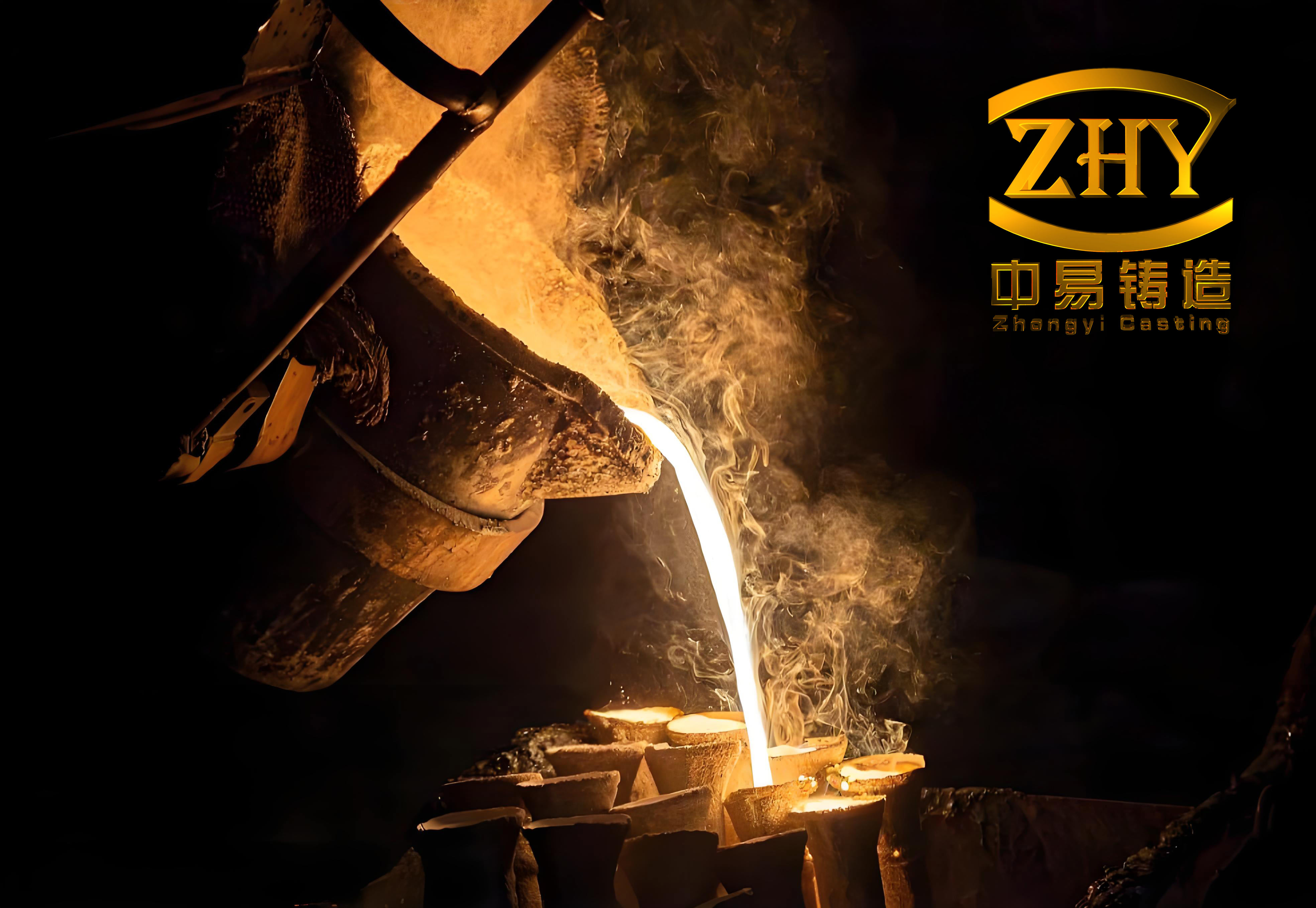
Casting was a critical phase in this precision lost wax casting project. The gating system was designed to also function as risers, with side and end reinforcement ribs integrated to minimize distortion. The solidification sequence was tailored for directional solidification: thin blades first, then inner/outer rings, and finally the risers. To optimize filling, the shell was preheated to about 850°C and buried in sand for casting, which improved thermal conditions. After pouring, the sand was removed after 30 minutes to accelerate cooling. Key parameters were balanced: higher pouring temperature for fluidity versus lower temperature to avoid surface burn-in. I selected an outlet temperature of 1580°C and a pouring temperature of 1540°C, with a pouring speed of 20 kg/s. Moreover, to ensure uniform filling and reduce thermal shock across the thin blades, a dual-ladle pouring technique was employed—simultaneously pouring at opposite gating positions on the inner and outer rings. This enhanced metal flow and venting in precision lost wax casting. The thermal dynamics can be expressed using the Chvorinov’s rule for solidification time:
$$ t = k \left( \frac{V}{A} \right)^n $$
where \( t \) is solidification time, \( V \) is volume, \( A \) is surface area, \( k \) is a mold constant, and \( n \) is an exponent (typically 2). For the blade sections, with high \( A/V \) ratios, solidification was rapid, while thicker sections required careful riser design. The table below outlines the casting parameters:
| Parameter | Value | Rationale |
|---|---|---|
| Shell Preheat Temperature | 850°C | Enhances fluidity and reduces thermal shock |
| Metal Outlet Temperature | 1580°C | Ensures superheat for low-alloy steel |
| Pouring Temperature | 1540°C | Balances fluidity and surface quality |
| Pouring Speed | 20 kg/s | Facilitates rapid filling for large cavity |
| Cooling Method | Sand burial for 30 min | Controls cooling rate to prevent defects |
The outcome of this precision lost wax casting effort was largely successful. The casting filled completely, with flow path dimensions meeting design specifications. However, post-casting inspection revealed some surface roughness and minor defects like sand inclusions and porosity after machining, which were repaired by welding. Overall, the component passed stringent quality checks, comparable to imported standards, demonstrating the viability of this precision lost wax casting method for large, one-off parts. The defects were analyzed as likely due to the use of recycled wax and the water glass shell system, which can introduce gases and impurities. This highlights areas for refinement in future precision lost wax casting applications.
Reflecting on this project, the assembled wax pattern approach offers significant advantages for precision lost wax casting in low-volume production. It eliminates die fabrication, reducing cost and lead time. However, to achieve higher quality, several improvements are proposed. First, using newly formulated wax patterns, such as blends of paraffin and stearic acid or medium-temperature waxes, would enhance surface finish and dimensional stability in precision lost wax casting. Second, adopting advanced shell systems like silica sol or ethyl silicate composite shells could improve surface smoothness and strength, reducing defects. Third, preheating the shell in a filled flask before pouring might allow lower pouring temperatures, yielding denser castings. These enhancements align with ongoing advancements in precision lost wax casting technology. The economic impact can be quantified by comparing costs: traditional die-based precision lost wax casting for such a part might involve upfront tooling costs exceeding $50,000, whereas this method reduces that to near zero, with only material and labor expenses. The formula for cost savings (\( C_s \)) is:
$$ C_s = C_d – (C_m + C_l) $$
where \( C_d \) is die cost, \( C_m \) is material cost for wax and shell, and \( C_l \) is labor for pattern machining and assembly. For single pieces, \( C_s \) is positive, making this precision lost wax casting technique economically attractive.
In conclusion, this precision lost wax casting project underscores the adaptability of lost wax processes to large-scale, complex components through innovative pattern-making. By integrating direct wax machining and assembly, we demonstrated a feasible path for single-item production without sacrificing the core benefits of precision lost wax casting. Future work should focus on optimizing materials and processes, such as implementing the suggested shell systems and wax upgrades, to further elevate quality. As industries demand more customized large parts, techniques like this will play a pivotal role in expanding the scope of precision lost wax casting. The success of this guide vane casting validates that with careful planning and execution, precision lost wax casting can transcend traditional limitations, offering a robust solution for niche manufacturing challenges. Throughout this endeavor, the principles of precision lost wax casting were continually applied and refined, proving its enduring relevance in modern metallurgy.