
The demand for high-integrity, complex aluminum alloy components in modern industries such as aerospace and defense has pushed traditional manufacturing methods to their limits. Producing intricate, thin-walled, and dimensionally precise sand casting products using conventional pattern-based sand casting often faces challenges related to mold tooling costs, lead times, and the geometric constraints of core assembly. In this work, I present a comprehensive case study on the development and manufacturing of a critical bridge bracket casting. The methodology integrates three-dimensional printing (3DP) of sand molds, advanced casting simulation for process design, and anti-gravity low-pressure casting to achieve a first-pass success in producing high-quality sand casting products.
The transition from traditional to digital foundry practices represents a significant leap. Conventional sand casting, while versatile, struggles with complex internal geometries that require intricate and often fragile core assemblies. The lead time and cost for pattern equipment for single or low-volume production of complex sand casting products can be prohibitive. The advent of binder jetting technology for sand molds—3DP—has revolutionized this space. It enables the direct digital fabrication of sand molds and cores as monolithic or optimally segmented structures, eliminating the need for physical patterns. This allows for unprecedented design freedom, rapid prototyping, and the production of geometries previously deemed “un-castable.” When combined with low-pressure casting, which offers superior metallurgical quality through controlled, turbulent-free filling and directional solidification under pressure, the potential for manufacturing premium sand casting products is greatly enhanced.
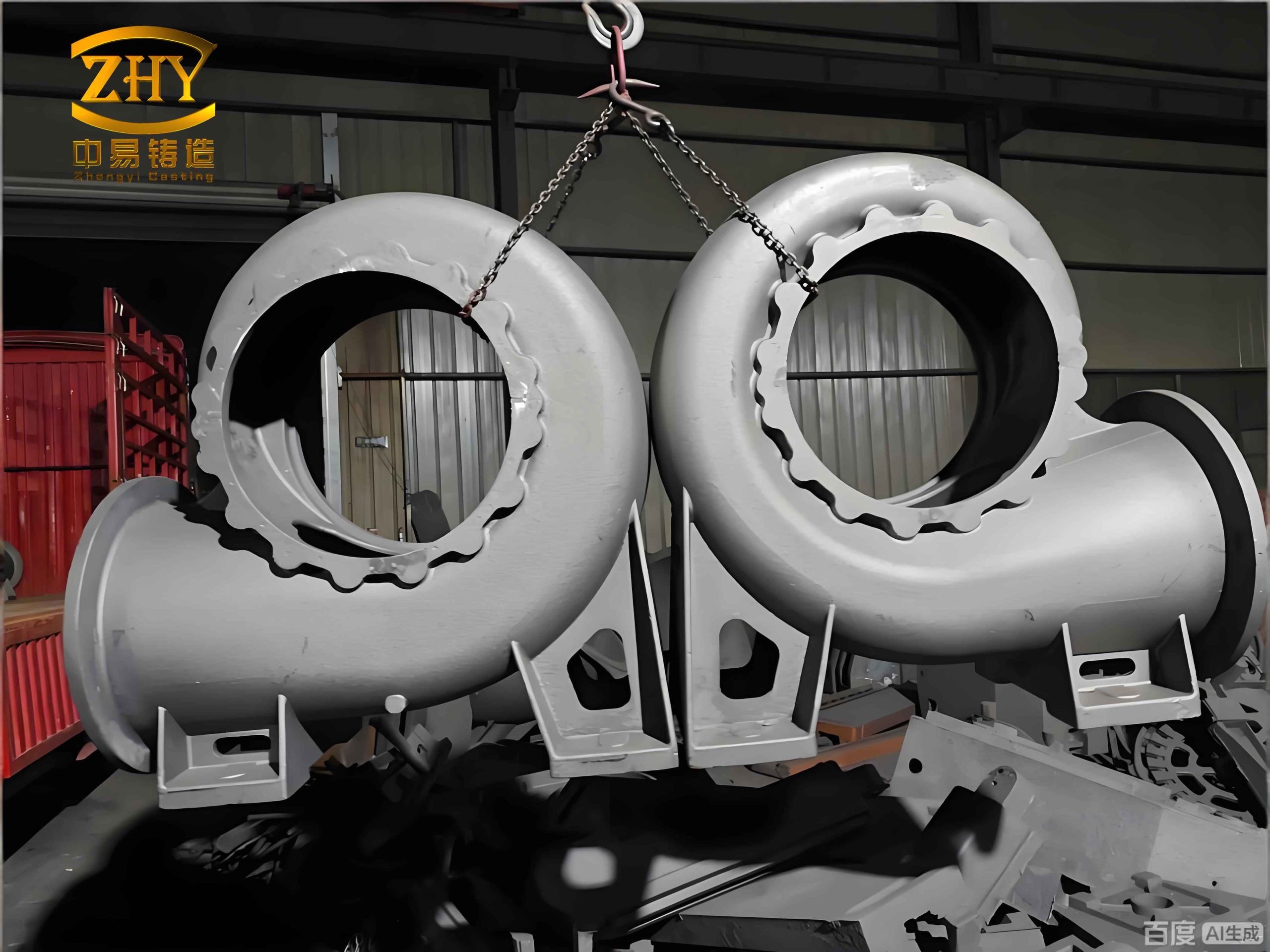
The specific component under investigation is a structural bridge bracket. This sand casting product is characterized by its substantial overall envelope combined with varying wall thicknesses and challenging internal features. The primary design specifications are summarized in the table below.
| Parameter | Specification |
|---|---|
| Material | ZL114A (Al-Si7Mg), per GB/T1173-2013 |
| Heat Treatment | T5 (Solution treated and artificially aged) |
| Overall Dimensions | 500 mm x 374 mm x 388 mm |
| Wall Thickness Range | 9 mm to 34 mm |
| As-Cast Dimensional Tolerance | Target: DCTG8 per GB/T6414-2017 |
| Mass | Approximately 27 kg |
| Internal Quality Requirement | Class II per GB/T9438-2013 (X-ray inspection) |
The key challenges in producing this sand casting product are immediately apparent: the presence of thick sections at the boss and mounting pad locations prone to shrinkage, and the complex internal cavity beneath the main body. This cavity is largely enclosed, connected to the outside only through small-diameter process holes, creating a “core-in-a-core” scenario that is extremely challenging for conventional core-making and handling, and a significant risk for core fracture and floatation during pouring.
My initial process design philosophy was centered on achieving controlled, sequential solidification. I selected the anti-gravity low-pressure casting process as the primary method. The filling equation for low-pressure casting is fundamental:
$$
P = \rho g h + \Delta P_{loss}
$$
where \( P \) is the applied pressure at the furnace, \( \rho \) is the molten alloy density, \( g \) is gravity, \( h \) is the effective height of the riser tube plus the mold cavity, and \( \Delta P_{loss} \) accounts for system friction and mold resistance. This process allows for a smooth, bottom-up fill, minimizing turbulence and oxide formation, and enables the application of a sustained pressure during solidification to feed shrinkage.
The gating system was designed as a combination of bottom gates and vertical slot gates. Four vertical slot gates (35 mm x 20 mm cross-section) were attached to the sides of the casting, fed from a common downsprue via four slag traps. The bottom of the internal cavity was fed through twelve small, tapered gates placed on the internal ribs. This design aimed to establish a strong thermal gradient, with the thick sections (top bosses and side pads) intended to solidify first, followed by the main body, and finally the gates and risers at the bottom. Thirty chill plates (20 mm thick) were strategically placed on all thick sections to increase the local solidification rate and reduce shrinkage porosity risk. The initial process parameters for simulation were set as follows.
| Simulation Parameter | Value |
|---|---|
| Alloy | ZL114A (AlSi7Mg0.6) |
| Pouring Temperature | 690 °C |
| Filling Time | 45 s |
| Mold Material | Silica Sand |
| Chills | Modeled as Iron, 20 mm thick |
The simulation of the filling process confirmed a very smooth, laminar flow front progression. The mold cavity filled steadily from the bottom gates upward, with no visible splashing or air entrapment. The solidification simulation revealed the intended thermal gradient. However, the prediction of shrinkage defects showed minor microporosity at the junction of the top tension rods (a temporary feature) and, more concerningly, a region of predicted shrinkage at the heavily gated bottom cavity floor. This indicated that despite the chills on the top bosses, the local heat concentration from the multiple bottom gates was creating a hot spot, jeopardizing the directional solidification for this critical area of the sand casting product.
Based on the simulation, I proceeded with the 3DP sand mold design. The mold was split into three boxes: cope, drag, and an intermediate box containing the monolithic core for the main internal cavity. This monolithic core design was a direct benefit of 3DP, ensuring excellent dimensional accuracy and core strength compared to an assembled core. A shrinkage allowance of 1.0% was applied. The mold was printed using 100-mesh silica sand with a layer thickness of 0.3 mm. After printing, the chills were bonded into pre-designed recesses in the cope, and the entire mold assembly was coated with a refractory wash and dried.
The first trial casting was produced using the designed low-pressure parameters. Metallurgical preparation of the ZL114A alloy included degassing using argon rotary impeller. The efficiency of degassing is often assessed by the Density Index (DI), calculated from reduced pressure test samples:
$$
DI = \left(1 – \frac{\rho_2}{\rho_1}\right) \times 100\%
$$
where \( \rho_1 \) is the density of a sample solidified under atmospheric pressure, and \( \rho_2 \) is the density of a sample solidified under reduced pressure (e.g., 80 mbar). A lower DI indicates lower hydrogen content. For this melt, a DI of 0.3% was achieved, indicating good gas quality. The low-pressure cycle was executed with a fill pressure of 50 kPa over 45 seconds, followed by an intensification pressure held for 600 seconds to promote feeding during solidification.
Post-casting analysis revealed several critical issues. Visually, sections of the casting wall corresponding to the internal cavity were missing, resulting in a condition known as “break-out.” Radiographic (X-ray) inspection confirmed sound material in the critical boss areas but showed unacceptable levels of shrinkage porosity on the bottom cavity floor. Dimensional inspection found that the internal cavity floor was not flat as designed but exhibited a warp of about 2 mm, and one critical radius dimension was out of specification.
A thorough root cause analysis was conducted. The breakout and warpage were directly linked. The monolithic core, while strong, had two large, isolated sand masses (forming the side cavities) connected only by thin bridges of sand through the small process holes. During pouring, the buoyant force (\(F_b\)) on these core sections can be estimated by:
$$
F_b = V_{core} \cdot (\rho_{metal} – \rho_{sand}) \cdot g
$$
where \(V_{core}\) is the volume of the submerged core section. This force, combined with the dynamic pressure of the molten metal, exceeded the strength of the connecting sand bridges, causing the core to fracture and float upward. This fracture led directly to the wall breakout and the distortion of the cavity geometry. The shrinkage on the bottom floor confirmed the simulation prediction—the area was a thermal hotspot. The gating design, while providing good fill, created an unfavorable thermal mass at the end of the solidification sequence.
This first trial, though not yielding a conforming sand casting product, provided invaluable data. The integrated approach of simulation and physical trial allowed for a rapid and precise diagnosis. The optimization strategy was then developed with clear objectives: 1) Increase core stability, 2) Eliminate the bottom thermal hotspot, and 3) Improve mold rigidity to resist core lift.
A multi-faceted optimization plan was implemented. First, the core design was modified by enlarging the connecting process holes between the isolated core sections, significantly increasing the cross-sectional area and thus the mechanical strength of these critical connections. The table below contrasts the changes.
| Feature | Initial Design | Optimized Design |
|---|---|---|
| Process Hole Diameters | 4 x Ø10 mm, 4 x Ø20 mm | 2 x Ø14 mm, 6 x Ø20 mm |
| Total Connection Area | ~ 1570 mm² | ~ 2450 mm² |
| Core Section Connectivity | Weak, prone to fracture | Robust, monolithic behavior |
Second, to address the shrinkage, ten additional chill plates (15 mm thick) were designed and placed directly on the external mold surface corresponding to the bottom cavity floor. These chills dramatically increased the local cooling rate, changing the solidification sequence. A follow-up simulation confirmed that the predicted shrinkage defect in this area was completely eliminated. The solidification time (\(t_s\)) for a section can be approximated by Chvorinov’s rule:
$$
t_s = B \cdot \left(\frac{V}{A}\right)^n
$$
where \(V\) is volume, \(A\) is surface area, \(B\) is a mold constant, and \(n\) is an exponent (typically ~2). By adding chills, we effectively increased the local \(A\) (cooling surface area), thereby reducing \(t_s\) for the bottom floor and moving its solidification ahead of the feeding gates.
Third, the mold assembly design was refined. The contact interface between the drag and the intermediate box was analyzed. In the initial design, the buoyant force from the drag was transferred primarily to a small ledge on the intermediate box core. This concentrated stress contributed to core fracture. The optimization involved modifying the parting line and increasing the contact area between the drag and the solid sand walls of the intermediate box, thereby distributing the lifting forces more evenly and providing better support against core floatation.
The optimized 3DP sand molds were printed, assembled, and used for a second casting trial. The results were markedly different. The casting was visually complete with no break-outs. Dimensional inspection showed all critical dimensions were now within the specified DCTG8 tolerance, with many actually achieving the tighter DCTG7 grade. Most importantly, radiographic inspection showed a complete absence of shrinkage porosity on the bottom cavity floor and continued soundness in the high-integrity boss areas. The mechanical properties from separately cast test bars met the ZL114A-T5 specification, as shown below.
| Property | Specification (GB/T1173-2013) | Actual Result (Average) |
|---|---|---|
| Tensile Strength | ≥ 290 MPa | 310 MPa |
| Yield Strength | — | 250 MPa |
| Elongation | ≥ 2 % | 3.2 % |
This validated process was successfully scaled for a small batch production, yielding consistent, high-quality castings. The successful manufacture of this complex bridge bracket highlights a powerful modern workflow for advanced sand casting products. The synergy between digital design (CAD), predictive simulation (CAE), and additive manufacturing (3DP) creates a closed-loop development cycle. Simulation guides the initial design but cannot capture all real-world phenomena, such as core fracture mechanics. The physical 3DP mold enables a rapid and cost-effective trial that reveals these issues. The insights gained then feed back into a refined digital model (for both part and process), leading to an optimized solution in the next iteration. This approach dramatically reduces the traditional “try-out” period and tooling costs associated with complex castings.
For foundries targeting high-value, low-to-medium volume markets, this integrated methodology is transformative. It shifts the competitive advantage from traditional pattern-making skill and expensive tooling investment towards digital engineering prowess and rapid prototyping capability. The ability to produce “impossible” cores, integrate conformal cooling channels (chills), and iterate designs quickly makes 3DP sand molding combined with processes like low-pressure casting an indispensable tool for the future of high-performance sand casting products.