
The production of large and geometrically complex gray iron castings for critical structural applications, such as machine tool columns and beds, presents significant manufacturing challenges. The primary objective is to achieve sound, dense castings free from shrinkage defects while simultaneously optimizing material yield and controlling production costs. Traditional casting process design often relies on qualitative judgment and iterative trial-and-error, which can be time-consuming, costly, and may lead to overly conservative designs with excessive risering. This paper presents a comprehensive, quantitative methodology for the casting process design of a large milling and boring machine column, a quintessential example of a gray iron casting. The core of this methodology lies in the synergistic application of numerical simulation for precise thermal analysis and established solidification theories for quantitative calculation of process parameters.
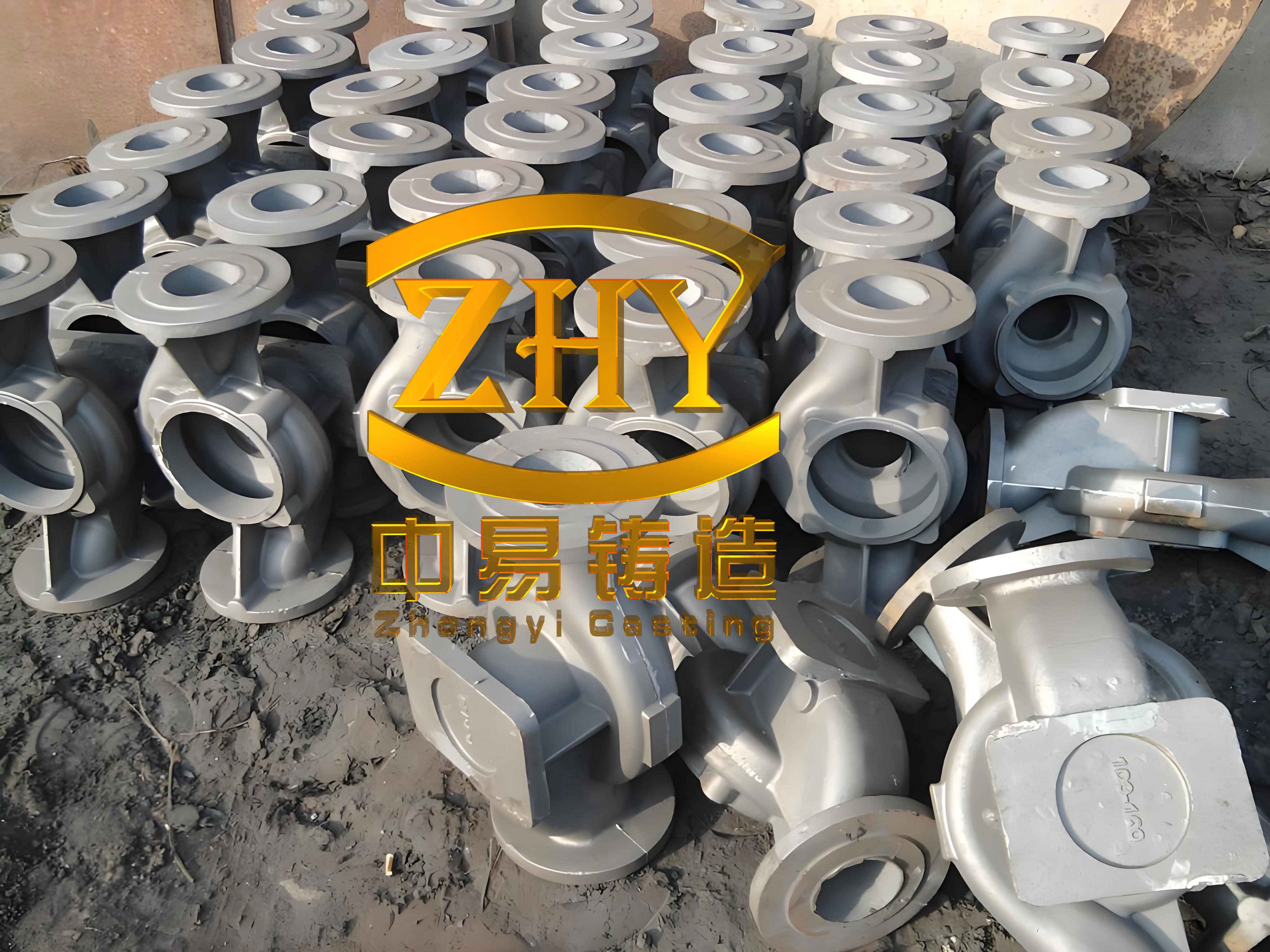
The casting under consideration is a major structural component made from grade HT300 gray iron. Its substantial dimensions (approximately 1990 mm x 900 mm x 1210 mm) and intricate internal ribbing create numerous thermal centers, or hot spots, where shrinkage porosity is likely to occur if not properly managed. The inherent graphitization expansion of gray iron provides a degree of self-feeding, but for large sections and complex junctions, this alone is insufficient to guarantee soundness. Therefore, a systematic approach combining external chilling, specialized molding materials, and strategically designed risers is essential for this gray iron casting.
1. Theoretical Foundation: Modulus Analysis and Proportional Solidification
The design philosophy is anchored on two key principles: Chvorinov’s rule for thermal analysis and the Proportional Solidification Theory for riser design. Chvorinov’s rule states that the solidification time ($t_f$) of a casting section is proportional to the square of its modulus ($M$), defined as the volume ($V$) to cooling surface area ($A$) ratio:
$$ t_f = k \cdot M^2 $$
where $k$ is a constant dependent on mold material and metal properties. Sections with a higher modulus solidify more slowly and are potential sites for shrinkage defects. For a complex 3D gray iron casting, manually calculating the modulus distribution is impractical. Instead, we leverage numerical simulation to compute a derived parameter, the Chvorinov’s Thermal Modulus ($M_{th}$), which approximates the geometric modulus locally based on thermal data from a simulation.
From a ProCAST solidification simulation output, $M_{th}$ can be calculated at any node by extracting the following parameters:
$$ M_{th} = \frac{2}{\sqrt{\pi}} \cdot \frac{T_{al,sol} – T_{mold,ini}}{\rho_{al,sol} \Delta H_{al}} \cdot \sqrt{k_{mold,ini} \rho_{mold,ini} c_{p,mold,ini}} \cdot \sqrt{t_{sol}} $$
Where:
- $T_{al,sol}$: Alloy solidus temperature.
- $T_{mold,ini}$: Initial mold temperature.
- $\rho_{al,sol}$: Alloy density at solidus.
- $\Delta H_{al}$: Enthalpy change of alloy from initial temp to solidus.
- $k_{mold,ini}, \rho_{mold,ini}, c_{p,mold,ini}$: Mold thermal conductivity, density, and specific heat at initial temperature.
- $t_{sol}$: Local solidification time.
This calculation, performed across the entire casting mesh, yields a detailed 3D map of thermal modulus, precisely identifying regions with $M_{th}$ values above a critical threshold (e.g., 2.5 cm), which are classified as hot spots requiring intervention.
For riser design on gray iron castings, the Proportional Solidification Theory is highly effective. It accounts for the contraction and expansion phases during solidification. Key design factors include the Casting Modulus ($M_c$), Casting Mass Perimeter Quotient ($Q_m$), and various empirical coefficients derived from the theory.
The Casting Mass Perimeter Quotient is calculated as:
$$ Q_m = \frac{G_c}{M_c^3} $$
where $G_c$ is the mass of the casting section fed by the riser. The solidification contraction time fraction ($P_c$) is given by:
$$ P_c = \frac{1}{e^{(0.5M_c + 0.01Q_m)}} $$
The riser neck modulus ($M_N$) and riser body modulus ($M_R$) are then determined using proportionality factors ($f_p$, $f_2$, $f_3$, $f_4$) from established handbooks:
$$ M_N = f_p \cdot f_2 \cdot f_4 \cdot M_c $$
$$ M_R = f_1 \cdot f_2 \cdot f_3 \cdot M_c $$
Where $f_2 = \sqrt{P_c}$. This quantitative approach allows for the design of risers that are precisely sized to match the feeding demand of the specific hot spot in the gray iron casting.
2. Quantitative Process Design Methodology
2.1 Step 1: Solidification Simulation and Modulus Mapping
The first step is to conduct a solidification-only simulation of the isolated casting. The material is defined as HT300 gray iron with appropriate thermophysical properties. The mold is defined as furan resin sand. The simulation is run to completion to obtain the full temperature history and local solidification times. Post-processing scripts are then used to extract the necessary fields (temperature, density, enthalpy change, etc.) and compute the $M_{th}$ field according to the formula above.
The resulting modulus map is analyzed using iso-surface plots. For instance, an iso-surface of $M_{th} \geq 2.5$ cm visually reveals all major hot spots. This objective, data-driven map replaces subjective judgment in identifying critical areas in the complex gray iron casting. The output typically shows hot spots at junctions, thick sections, and isolated heavy bosses.
| Hot Spot Location | Average Modulus ($M_{th}$) [cm] | Proposed Technical Solution | Rationale |
|---|---|---|---|
| Bottom & Mid-Section Junctions (A, B) | ~2.6 – 3.0 | Direct Chill Placement | Accessible for external chilling to increase cooling rate. |
| Large Side Boss (C) | > 3.0 | Direct Chill Placement | Major isolated thermal mass; requires strong chilling. |
| Top Section Junctions (D) | ~2.6 | Joint Flash Riser | Top location ideal for riser placement; feeding path is vertical. |
| Internal Rib Network (E) | ~2.0 – 2.5 | Chromite Sand Cores + Chill | Complex, inaccessible geometry; chromite sand provides internal chilling. |
2.2 Step 2: Quantitative Riser Design for Identified Hot Spots
For hot spots designated for riser feeding (like location D), the modulus map provides the key input parameters. The region of the hot spot is isolated using the modulus cutoff. The simulation results are queried to find the average $M_{th}$ within this region and the total volume of metal where $M_{th}$ exceeds the cutoff. For the top junction in our example:
- Average $M_c$ (approximated from $M_{th}$) = 2.6 cm
- Volume of metal ($V_{c}$) = 3700 cm³
- Mass of casting section ($G_c$) = $V_{c} \times \rho$ = 3700 cm³ $\times$ 6.8e-3 kg/cm³ = 25.16 kg
Using the formulas from the Proportional Solidification Theory:
$$ Q_m = \frac{25.16}{2.6^3} = 1.43 \text{ kg/cm}^3 $$
$$ P_c = \frac{1}{e^{(0.5 \times 2.6 + 0.01 \times 1.43)}} = 0.27 $$
$$ f_2 = \sqrt{P_c} = \sqrt{0.27} = 0.52 $$
Selecting standard coefficients $f_p=0.5$, $f_4=0.8$, the riser neck modulus is:
$$ M_N = f_p \cdot f_2 \cdot f_4 \cdot M_c = 0.5 \times 0.52 \times 0.8 \times 2.6 = 0.54 \text{ cm} $$
For two risers feeding related sections, the balance factor $f_1$ is adjusted. With a base $f^*_1=2$ for one riser, for two risers (N=2):
$$ f_1 = \frac{(f^*_1 – 1)}{N} + 1 = \frac{(2-1)}{2} + 1 = 1.5 $$
Using $f_3=1.1$, the riser body modulus is:
$$ M_R = f_1 \cdot f_2 \cdot f_3 \cdot M_c = 1.5 \times 0.52 \times 1.1 \times 2.6 = 2.23 \text{ cm} $$
These modulus values ($M_R$, $M_N$) are then used to select a standardized riser geometry, in this case, a joint flash riser, with dimensions scaled to meet the calculated modulus. This ensures the riser solidifies later than the hot spot and provides adequate feed metal volume, precisely tailored for this specific gray iron casting.
2.3 Step 3: Gating System Design Based on Proportional Solidification
The gating system must facilitate smooth filling and can also act as a liquid feeder during early solidification. For heavy gray iron castings, a bottom-gating system is often preferred to minimize turbulence and mold erosion. The design is quantified using empirical formulas from the Proportional Solidification Theory.
For a casting mass $G_L$ (approx. 5000 kg for a two-casting mold), average wall thickness $\delta$ (30 mm), the pouring time ($t$) is calculated as:
$$ t = S_1 \cdot \sqrt[3]{\delta \cdot G_L} $$
where $S_1$ is a coefficient (1.8 for medium-large castings). This gives $t \approx 96$ seconds.
The effective filling pressure head at the ingate ($h_p$) is critical and depends on the gating ratio and sprue height. For a bottom-gated system with a sprue height $H_0$:
$$ H_p = H_0 – \frac{h_c}{8} $$
$$ h_p = \frac{k_2^2}{1 + k_1^2 + k_2^2} \cdot H_p $$
where $h_c$ is casting height, and $k_1$, $k_2$ are effective area ratios for the sprue/runner and runner/ingate, respectively, derived from the chosen gating ratio (e.g., $A_{sprue}:A_{runner}:A_{ingate} = 1.2:1.5:1.0$) and respective flow coefficients ($\mu$).
Finally, the total ingate area ($\Sigma A_{ingate}$) is calculated based on the mass, pouring time, flow coefficient ($\mu$), and effective pressure head:
$$ \Sigma A_{ingate} = \frac{G_L}{0.31 \cdot \mu \cdot t \cdot \sqrt{h_p}} $$
This yields a specific, optimized area which is then divided into an appropriate number of ingates. The complete gating design ensures controlled filling and defines the period during which it can provide liquid feed metal to the solidifying gray iron casting.
| Parameter | Symbol | Value | Unit |
|---|---|---|---|
| Total Metal Mass | $G_L$ | ~5000 | kg |
| Calculated Pouring Time | $t$ | 96 | s |
| Gating Ratio (Selected) | $A_s : A_r : A_i$ | 1.2 : 1.5 : 1.0 | – |
| Effective Pressure Head | $h_p$ | ~444 | mm |
| Total Ingate Area | $\Sigma A_{ingate}$ | 42 | cm² |
| Number of Ingates | $n$ | 8 | – |
| Area per Ingate | $A_{ingate}$ | 5.3 | cm² |
3. Integrated Simulation and Validation of the Complete Process
With all process elements designed—chills, chromite sand cores, risers, and gating system—a full coupled filling and solidification simulation is performed. This validates the integrated design for the entire gray iron casting process.
3.1 Filling Analysis
The simulation shows a sequential and tranquil fill. Metal enters the mold cavity from the bottom ingates and rises steadily, avoiding any “waterfall” effect that could cause turbulence and gas entrapment. The gating system fills completely without air entrainment. The smooth fill pattern confirms the suitability of the bottom-gating design for this large gray iron casting, promoting favorable temperature gradients and facilitating slag flotation.
3.2 Solidification and Feeding Analysis
The solidification sequence clearly demonstrates the effectiveness of the chosen techniques. Regions with direct chills and chromite sand show dramatically accelerated cooling, effectively eliminating these hot spots as potential shrinkage sites. The analysis of the liquid surface height in the pouring basin provides crucial insight into the feeding dynamics.
By tracking the metal level in the sprue cup over simulated time, we can identify distinct feeding phases for the gray iron casting:
- Liquid Feeding Phase (0-40% Solidified): The metal level in the sprue drops continuously, indicating that the liquid metal in the gating system is actively feeding the contracting casting. The ingates remain open.
- Transition Phase (~40-50% Solidified): The metal level stabilizes. The ingates begin to freeze off, halting liquid feed from the gating system.
- Graphitic Expansion Self-Feeding Phase (50-100% Solidified): After gate freeze-off, the internal feeding demand is met by the expansion associated with graphite precipitation during the eutectic solidification of the gray iron casting. This is observed in the simulation as small, nascent porosity forms and then disappears as the expansion compensates for the remaining contraction.
- Riser Feeding Phase: Concurrently, the designed joint flash risers, having a higher modulus than the casting hot spots, remain liquid longest. They provide feed metal to their specific junctions until they themselves solidify completely, as evidenced by a fully developed shrinkage cavity within the riser body in the final simulation results.
The final shrinkage prediction shows no porosity within the main body of the casting. The only significant shrinkage cavities are located within the risers and the top of the gating system, confirming that the risers performed their function perfectly and that the gating system contributed to feeding before freeze-off. The successful soundness of the gray iron casting validates the entire quantitative design process.
| Feeding Mechanism | Primary Activation Period (% Total Solidification) | Role in Gray Iron Casting Soundness |
|---|---|---|
| Gating System Liquid Feed | 0% – ~40% | Compensates for initial liquid contraction and early solidification shrinkage. |
| Graphite Expansion (Self-Feeding) | ~50% – 100% | Internal compensation for shrinkage, unique to gray irons; eliminates micro-porosity. |
| Riser Liquid Feed | ~30% – 100% (Riser-specific) | Compensates for shrinkage in designated hot spots; risers solidify last. |
| Chill / Chromite Sand Action | 0% – 100% | Prevents formation of hot spots by accelerating local solidification, eliminating feeding demand. |
4. Conclusion
This work demonstrates a robust, quantitative framework for the process design of large and complex gray iron castings. The methodology moves beyond qualitative guesswork by integrating advanced numerical simulation directly with foundational solidification theory. Key outcomes include:
- Precision Hot Spot Identification: The calculation of the Chvorinov’s Thermal Modulus ($M_{th}$) field from a solidification simulation provides an objective, quantitative map of critical regions, forming the basis for all subsequent design decisions for the gray iron casting.
- Quantitative Riser Sizing: By extracting the average modulus and metal volume from the simulated hot spot, riser dimensions can be calculated precisely using Proportional Solidification Theory, ensuring adequate feed metal with minimal waste.
- Optimized Complementary Techniques: The modulus map guides the optimal placement of chills and chromite sand, providing targeted cooling for hot spots where risers are impractical, thereby reducing the overall feeding burden.
- Validated Feeding Dynamics: Full-process simulation confirms the designed feeding sequence—initial liquid feed from the gating system, followed by riser feeding and graphite expansion—works synergistically to produce a sound gray iron casting.
This integrated approach ensures high casting quality by preventing shrinkage defects while significantly improving yield and reducing costs through the elimination of over-design. It represents a significant step towards a fully digital, predictive, and quantitative foundry engineering practice for demanding gray iron casting applications.