
Abstract
Based on the stringent requirements for casting precision and surface quality of hoisting box castings, this study focuses on the process design and simulation analysis of complex steel castings for such applications. The sand casting process was determined, and the molding materials, casting process parameters, gating system, and feeding system were designed and optimized. CAD and 3D software were utilized to create casting process diagrams and three-dimensional models. Casting simulation software was employed to predict and control shrinkage defects, significantly enhancing the quality of the steel castings. This paper provides valuable insights into the process design and optimization of complex steel castings for hoisting boxes.
1. Introduction
The hoisting box, as a crucial component in elevator lifting devices, plays a vital role in transmission boxes, gearboxes, and reduction gearboxes. Due to its irregular wall thickness, complex shape, and high mechanical property requirements, the casting of such hoisting boxes poses significant challenges. This study aims to design and optimize the casting process for these complex steel castings to improve production efficiency, simplify the molding and coring process, and enhance casting quality.
2. Structure and Material of the Hoisting Box
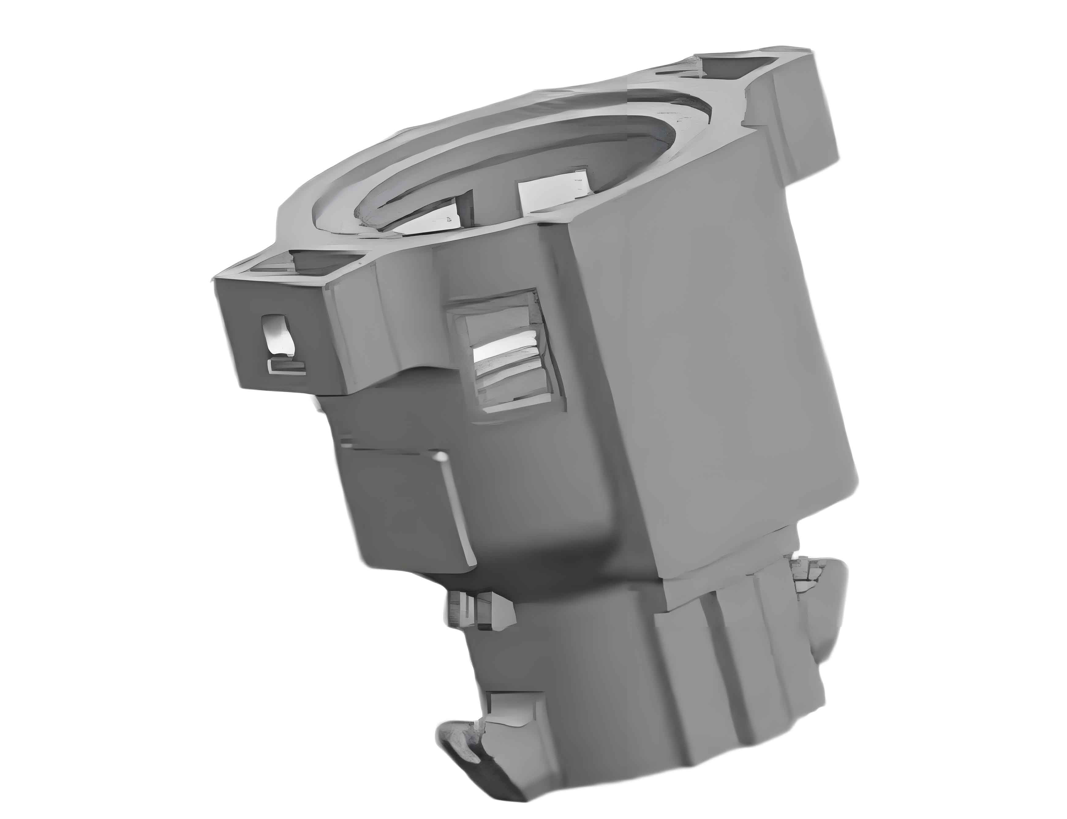
2.1 Structure of the Hoisting Box
The hoisting box casting has a length of 1088 mm, a cylindrical diameter of 400 mm, a maximum wall thickness of approximately 240 mm, a minimum wall thickness of 45 mm, and a net weight of about 1060 kg. It features a cylindrical shape with thin upper and thick lower sections. The external circumference includes square protrusions, and the bottom has inverted hook-shaped guide grooves that affect mold stripping. Additionally, numerous holes and grooves need to be cast into the component.
2.2 Material of the Hoisting Box
The material of the hoisting box casting is ZG25CrNiMo, a low-alloy heat-resistant steel with good microstructural stability and excellent process performance.
3. Casting Process Design
3.1 Molding Materials
Based on the casting dimensional tolerances and technical requirements, furan resin sand was selected for both the mold and cores. The sand mixture ratios are presented in Table 1.
Table 1. Sand Mixture Ratios
| Material | Old Sand (%) | New Sand (%) | Resin (%) | Curing Agent (as % of Resin) | Tensile Strength (MPa) |
|---|---|---|---|---|---|
| Mold Sand | 40-65 | 35-60 | 1.5-1.7 | 30 | 0.4-0.7 |
| Core Sand | 60-70 | 30-40 | 1.7-2.0 | 30 | 0.7-1.2 |
3.2 Casting Process Parameters
3.2.1 Selection of Parting Line
Based on the structural characteristics of the casting, two parting line options were considered: at the top surface and at the middle of the largest cross-section. Option 1, although at the largest contour cross-section, may lead to mismatching when the upper and lower molds are closed and casting defects such as fins at the parting line, affecting the cleaning process and appearance quality. Option 2, with the entire casting in one sandbox, avoids mismatching, and with the casting inverted, the thicker upper section and thinner lower section facilitate the placement of feeding systems and ensure sequential solidification.
3.2.2 Selection of Pouring Position and Pouring System Design
A bottom-pouring system was adopted to ensure smooth mold filling, reduce steel oxidation, minimize impact on the sand cores, and avoid sand inclusion defects. A funnel-shaped pouring cup was used due to its simple structure, low metal consumption, and high process yield. Ordinary top-open feeding cups were chosen. Based on the open pouring system ratio for steel castings (ΣF直:ΣF横:ΣF内 = 1:1.6:2), the cross-sectional areas of the pouring system components were calculated using the flow rate method, with ΣF直 = 13 cm², ΣF横 = 21 cm², ΣF内 = 26 cm², and a pouring time of 49 seconds. The design features a cylindrical sprue, trapezoidal cross-section runner, semi-circular outer contour runner, and rectangular ingates, with five evenly distributed ingates. A ceramic foam filter was placed at the bottom of the sprue to filter the molten steel during pouring.
3.3 Core Process Design
For the hoisting box, furan resin sand was mainly used for core making. Core 1 forms the inner cavity of the hoisting box, while Cores 2 and 3 shape the handle position and external square protrusion contours of the box. Core 3’s core head was designed as a movable block for convenient molding and accurate positioning.
3.4 Core Shape and Ventilation
To ensure accurate core assembly and box closing, core heads were provided on the main cores. Although Core 1 is complex, it was made as a single integral core to ensure efficient assembly and high positioning accuracy. Considering the relatively large casting size, vent holes were drilled at the thickest parts of the cores. In Core 1, ventilation ropes were wrapped along the core backbone, and vent holes were drilled at the top of the core heads to facilitate sufficient ventilation under heat, preventing the occurrence of invasive porosity.
4. Casting Process Simulation Analysis
4.1 Mold Filling Process Simulation
The mold filling time simulation results that it takes approximately 48 seconds for the molten metal to enter and fill the mold cavity, consistent with the calculated results. The velocity cloud diagram indicates that the molten metal entering the mold cavity through the ingates at the bottom of the bottom-pouring system has a relatively low velocity, with consistent values. The velocity in the sprue is higher. As the filling time increases, the metal rises smoothly and synchronously, with no turbulence or chaotic filling. The highest point of the casting, the feeding cup, is filled last, and the metal at the large cross-section flows in laminar form. The entire filling process achieves sequential filling and smooth pouring.
4.2 Solidification Shrinkage Analysis
The solid fraction and shrinkage volume during the solidification process of the hoisting box. It is evident that the areas with lower solid fractions are the thick regions at the root of the feeding cup and the connections between the internal ribs and the inner cavity. The feeding cup cannot effectively feed the hot spots. The shrinkage volume simulation results also indicate larger shrinkage volumes at the thick positions at the root of the feeding cup, leading to the formation of larger shrinkage cavities. This further demonstrates that the modulus of the feeding cup is designed smaller than that of the casting, and the thicker parts of the casting solidify later than the feeding cup, resulting in shrinkage cavities. Additionally, the hot spots at the ribs are not effectively fed due to their distance from the feeding cup and the small modulus of the feeding channels, which solidify prematurely, causing obstruction in the feeding channels. Therefore, shrinkage cavities persist, necessitating optimization of the feeding cup design combined with the use of chillers to reduce shrinkage and porosity.
(a) Solid Fraction Analysis
(b) Shrinkage Volume Analysis
5. Optimization of Feeding Process
To enhance the feeding efficiency and reduce defects such as shrinkage cavities in the complex steel casting of the hoisting box, an optimization of the feeding process was undertaken. The primary focus was on modifying the design of the feeding cup and incorporating external chillers.
The feeding cup was enlarged to increase its capacity to supplement liquid and solidification shrinkage. This modification involved transforming the original annular-shaped feeding cup into a solid shape, accompanied by an increase in its height. This change aimed to provide a more substantial source of molten metal to compensate for shrinkage during the solidification process.
Furthermore, to address the issue of slow local cooling, which could lead to shrinkage cavities, external chillers were designed and strategically placed at the hot spots of the casting. These chillers served to accelerate local cooling, thereby reducing the local modulus and facilitating sequential solidification. By doing so, the risk of shrinkage defects was minimized.
The specific design of the external chillers involved determining their size and placement. The area of each chiller was calculated to be 21,000 square millimeters, with a total of four chillers utilized. Their precise locations were identified and marked. This arrangement ensured that the chillers effectively targeted the areas most susceptible to shrinkage, thereby enhancing the overall quality of the casting.
The incorporation of these design changes led to a significant improvement in the feeding process. The enlarged feeding cup, combined with the strategic placement of external chillers, effectively addressed the challenges posed by shrinkage and local cooling rates. This optimized design not only reduced the incidence of shrinkage defects but also contributed to a more uniform and controlled solidification process.
In summary, the optimization of the feeding process involved transforming the feeding cup from an annular to a solid shape with increased height, and incorporating external chillers at strategic locations. These changes collectively enhanced the feeding efficiency and reduced defects, ultimately leading to improved casting quality.