
The production of large-scale grey iron castings presents a significant challenge in foundry engineering, primarily due to the inherent risk of shrinkage defects like porosity and cavities. These defects compromise the structural integrity and service performance of the component, leading to potential failures and economic losses. In this context, the use of Computer-Aided Engineering (CAE) simulation has become indispensable for predicting and eliminating such issues prior to the actual manufacturing process. This article details my first-hand experience in optimizing the casting process for a substantial grey iron disk through numerical simulation. The component under investigation was a large disk with an outer diameter of 1600 mm, a thickness of 150 mm, and a weight of approximately 766 kg, manufactured from grade HT150 grey iron. The primary technical requirement was the complete absence of shrinkage porosity, shrinkage cavities, sand inclusions, cracks, and gas holes.
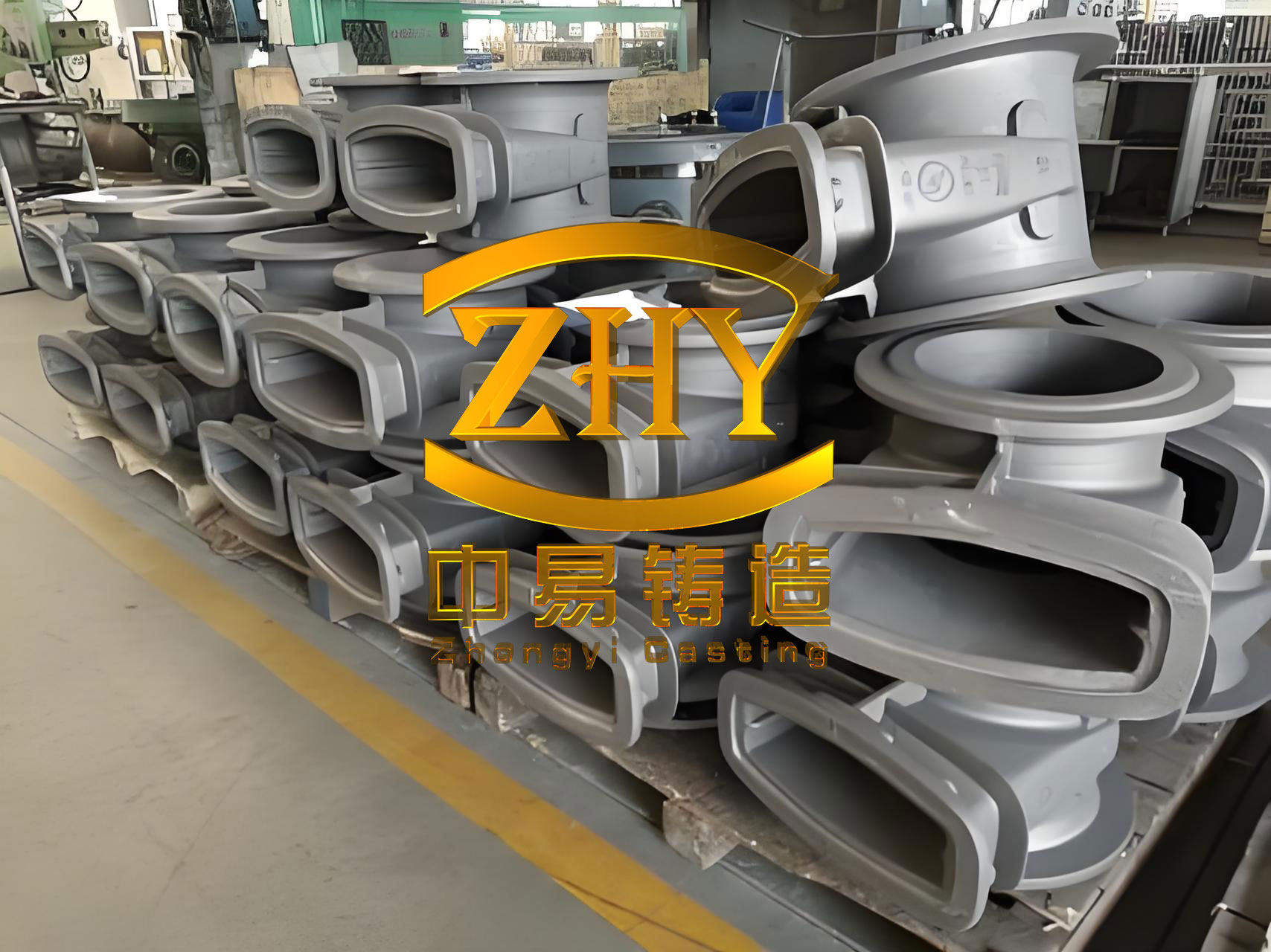
Traditionally, developing a sound process for such a large grey iron casting relied heavily on empirical knowledge and prototype trials, which were both time-consuming and costly. Numerical simulation technology transforms this approach by solving the fundamental equations of heat transfer, fluid flow, and solidification. It allows for the virtual visualization of the entire casting process—filling, solidification, and cooling—thereby enabling a comprehensive quality assessment of different gating and feeding system designs on a computer. This proactive methodology facilitates the identification of potential defect locations, allowing for iterative design improvements until an optimal solution is found. For this grey iron casting project, I employed ViewCast simulation software to evaluate and refine three distinct process schemes, ultimately arriving at a robust and efficient production method.
Fundamentals of Solidification Simulation for Grey Iron
The accuracy of any simulation hinges on correctly modeling the material’s behavior. Grey iron possesses unique solidification characteristics due to its graphite precipitation. During the eutectic reaction, the expansion associated with graphite formation can partially or fully compensate for the volumetric shrinkage of the remaining liquid, a phenomenon known as “self-feeding.” The efficiency of this compensation depends on factors like cooling rate, chemical composition (particularly carbon equivalent), and the mold’s rigidity. The key governing equation for simulating the solidification process is the heat conduction equation, which includes the latent heat release:
$$
\rho c_p \frac{\partial T}{\partial t} = \nabla \cdot (k \nabla T) + \rho L \frac{\partial f_s}{\partial t}
$$
Where:
- $\rho$ is the density (kg/m³),
- $c_p$ is the specific heat capacity (J/(kg·K)),
- $T$ is the temperature (K),
- $t$ is the time (s),
- $k$ is the thermal conductivity (W/(m·K)),
- $L$ is the latent heat of fusion (J/kg),
- $f_s$ is the solid fraction.
The prediction of shrinkage defects is often based on tracking the evolution of isolated liquid regions or using criteria functions like the Niyama criterion, adapted for grey iron casting. A simplified version of the thermal gradient-based criterion can be expressed as:
$$
G / \sqrt{\dot{T}} \geq C
$$
Where $G$ is the temperature gradient (K/m), $\dot{T}$ is the cooling rate (K/s), and $C$ is a critical value specific to the alloy. Regions where this value falls below the threshold are prone to micro-porosity.
Initial Process Scheme (Scheme I) and Simulation Analysis
The first design approach was guided by the principle of simultaneous solidification, considering the disk’s relatively thin but large horizontal geometry. The process parameters for Scheme I were established as follows:
- Gating System: A bottom-gated, pressurized system was designed. Molten metal was introduced from the bottom through a sprue, horizontal runner, and three ingates to promote a calm fill and minimize turbulence. The cross-sectional area ratio was set as Sprue : Runner : Ingate = 1.15 : 1.1 : 1. Using Osann’s formula, the calculated minimum ingate area was $F_{ingate} = 16 \, \text{cm}^2$.
- Molding & Pouring: Self-setting sand was selected for its high rigidity. The entire grey iron casting was placed in the cope (upper mold), with the large flat surface facing down. The pouring temperature range was 1340–1370°C.
- Feeding: Relying entirely on the self-feeding capacity of grey iron, no feeder (riser) was used in this scheme. The hope was that the eutectic expansion would compensate for shrinkage in the central hub, which was the thickest section.
The 3D model was meshed with approximately 2 million elements, and the simulation was run with standard boundary conditions (mold initial temperature of 25°C). The defect prediction results were clear and concerning. Significant shrinkage porosity and cavities were predicted precisely in the central hub area, forming an isolated liquid “hot spot.” This indicated that for this specific geometry and volume, the inherent graphite expansion was insufficient to counteract the thermal contraction. The lack of an external feed source made this defect inevitable. The simulation of Scheme I conclusively demonstrated that a no-riser approach was unsuitable for this particular large grey iron casting.
Revised Process with Riser and Chills (Scheme II)
Based on the failure of Scheme I, the strategy shifted from simultaneous to directional solidification. The goal was to force the central hub, the last section to solidify, to be fed by an external reservoir of liquid metal. Scheme II incorporated the following modifications:
- Addition of a Riser: A ring-shaped feeder with dimensions of approximately Ø200 mm x 160 mm in height was placed on top of the central hub. Its purpose was to remain molten longer than the casting, providing liquid metal to feed the shrinkage.
- Application of Chills: To accelerate cooling at specific junctions and potentially improve feeding paths, eight cylindrical grey iron chills (Ø120 mm x 50 mm) were placed at the intersections of the ribs on the bottom surface.
- The gating system design, pouring temperature, and mold material from Scheme I were retained.
The simulation of Scheme II showed a partial improvement. The ring riser did provide some feeding, and the chills accelerated local solidification. However, the defect was not eliminated; it was merely relocated. The simulation predicted shrinkage defects at the junction between the riser and the casting, a classic symptom of a “necking” or prematurely sealed feeding channel. This result pointed to two likely issues: 1) The riser’s volume or geometric modulus might have been insufficient to sustain feeding until the critical section solidified completely, and 2) The solidification path from the casting into the riser was not optimally controlled, causing the connection to freeze shut too early. While a step in the right direction, Scheme II was still not viable for producing a sound grey iron casting.
Optimized Final Process (Scheme III) and In-Depth Simulation
The analysis of Schemes I and II provided crucial insights. For Scheme III, a more radical layout change was adopted to establish a clear and robust thermal gradient toward the riser.
- Mold Layout Reversal: The entire grey iron casting was placed in the drag (lower mold), with its large flat surface facing upward. This positioned the thick central hub closer to the top of the mold.
- Riser Re-design: A single, larger cylindrical side riser (Ø250 mm x 180 mm) was placed directly on top of the central hub at the parting line. This provided a greater volume of feed metal and a more direct connection to the hot spot.
- Gating Adjustment: Metal was still introduced in three streams, but now from the parting plane into the side of the disk’s rim. The chills from Scheme II were removed, as the rib intersections were no longer primary concern areas under the new solidification pattern.
The simulation of the solidification sequence for Scheme III was revealing. The following table summarizes key timestamps from the thermal analysis:
| Time Elapsed (s) | Solidification Stage Description | Thermal Gradient Status |
|---|---|---|
| 0 – 3800 | Rapid solidification of thin sections: rim, ribs, and ingates. The gating system freezes early. | Strong gradient established from edges toward center. |
| 3800 – 5100 | Solidification front progresses inward toward the central hub. Small isolated liquid pools form at rib junctions but are eliminated by graphitic expansion. | Gradient remains positive toward the hub. Self-feeding is effective in thin junctions. |
| 5100 – 9000 | The hub itself begins to solidify radially inward. The riser connection remains fully open and liquid. | Clear directional solidification: Casting → Riser neck → Riser body. |
| 9000 – 12000 | Final solidification of the riser neck and the riser itself. The hub is fully solid. | Riser is the last part to solidify, confirming its effectiveness. |
The final defect prediction plot for Scheme III confirmed the success of the design. No shrinkage porosity or cavities were indicated within the body of the grey iron casting. All predicted shrinkage was successfully displaced into the riser, which acted as a perfect sacrificial reservoir. The thermal analysis proved that a positive temperature gradient ($G > 0$) was maintained from the farthest point of the casting all the way to the top of the riser throughout the solidification process. This ensured an open “feeding channel” until the very end. Furthermore, the simulation validated that the graphitic expansion in the thinner sections (rib junctions) was sufficient for self-compensation, eliminating the need for chills and simplifying the process.
The efficiency of the feeding system can be conceptually evaluated using the modulus method. The geometric modulus (Volume/Surface Area) of the central hub ($M_{hub}$) and the riser ($M_{riser}$) should follow the relationship $M_{riser} > M_{hub}$ for effective feeding. In our optimized scheme, the riser’s dimensions satisfied this criterion, whereas in Scheme II, the ring riser likely had an insufficient modulus. The solidification time ($t_s$) of a section can be estimated by Chvorinov’s rule:
$$
t_s = B \cdot \left( \frac{V}{A} \right)^n = B \cdot M^n
$$
Where $B$ and $n$ are constants dependent on mold material and metal properties. Scheme III ensured that $t_{s,riser}$ was greater than $t_{s,hub}$, creating the necessary time window for feeding.
Comparative Analysis and Production Validation
The following table provides a consolidated comparison of the three investigated schemes, highlighting the critical differences in approach and outcome for this grey iron casting.
| Feature | Scheme I | Scheme II | Scheme III (Optimized) |
|---|---|---|---|
| Philosophy | Simultaneous Solidification / No Feeding | Directional Solidification with Auxiliary Aids | Strong Directional Solidification |
| Casting Orientation | Flat face down (in Cope) | Flat face down (in Cope) | Flat face up (in Drag) |
| Feeding System | None (Reliance on self-feeding) | Ring riser on top + Chills on bottom | Cylindrical side riser on hub, no chills |
| Key Simulation Prediction | Major shrinkage in central hub | Shrinkage at riser-casting junction | No internal defects; shrinkage in riser only |
| Primary Issue | Insufficient self-feeding for mass | Inadequate riser modulus & poor feeding path | Optimal thermal gradient and feeding |
| Process Complexity | Low | High (chills, complex riser) | Moderate |
| Material Yield | Potentially High (no riser) | Low (riser + chills, defective casting) | Good (effective riser, sound casting) |
Based on the promising results from the Scheme III simulation, the process was released for trial production. A batch of 16 disk castings was produced following the optimized parameters. The results were excellent: all 16 castings were found to be sound upon visual inspection and non-destructive testing. Subsequent machining operations confirmed the absence of subsurface shrinkage defects. The mechanical properties met the HT150 grade specifications, validating the simulation predictions and the effectiveness of the optimized process for this challenging grey iron casting.
Conclusion and Broader Implications
This comprehensive study underscores the transformative power of numerical simulation in modern foundry practice, especially for complex components like large grey iron casting. The journey from Scheme I to Scheme III demonstrates a systematic, science-based approach to problem-solving:
- Scheme I failed because the assumption of adequate self-feeding through graphitic expansion was incorrect for the significant thermal mass of the central hub.
- Scheme II failed due to an undersized and ill-positioned riser that created a premature freezing junction, despite the addition of chills.
- Scheme III succeeded by fundamentally re-orienting the casting to establish a natural thermal gradient and employing a correctly sized riser placed on the hottest spot, ensuring a clean feeding path until final solidification.
The successful outcome hinged on leveraging simulation to understand not just the final state, but the dynamic progression of the solidification front. It allowed for the intelligent integration of grey iron’s self-feeding characteristics in thin sections while providing robust external feeding for heavy sections. This project serves as a compelling case for the mandatory use of CAE simulation in the development of gating and feeding systems for critical grey iron casting components, ensuring first-pass success, reducing scrap rates, and delivering reliably high-quality products.