
In the field of metal casting, grey iron casting remains a cornerstone for industrial components due to its excellent machinability, damping capacity, and cost-effectiveness. However, producing high-strength, heavy-section grey iron castings presents significant challenges, particularly when dealing with extreme thickness variations. As a casting engineer specializing in grey iron casting, I have encountered numerous cases where shrinkage defects jeopardize product integrity. This article shares my firsthand experience in addressing shrinkage issues in a critical energy system component—a bearing housing made of HT300 grey iron casting. The insights drawn from this case are applicable to a wide range of thick-section grey iron casting applications.
The component in question is a bearing housing used in drainage and energy power systems. This grey iron casting weighs 4000 kg and is classified as HT300 grade, requiring high tensile strength and freedom from defects such as porosity, cracks, sand inclusions, and shrinkage. The geometry is characterized by drastic wall thickness variations: a base face with a thickness of 250 mm, minimal sections of 30 mm at certain arcs, and predominant walls of 80 mm. Such disparities in grey iron casting often lead to uneven cooling, high residual stresses, and difficulty in feeding during solidification, making it prone to cracks and shrinkage cavities in thick zones.
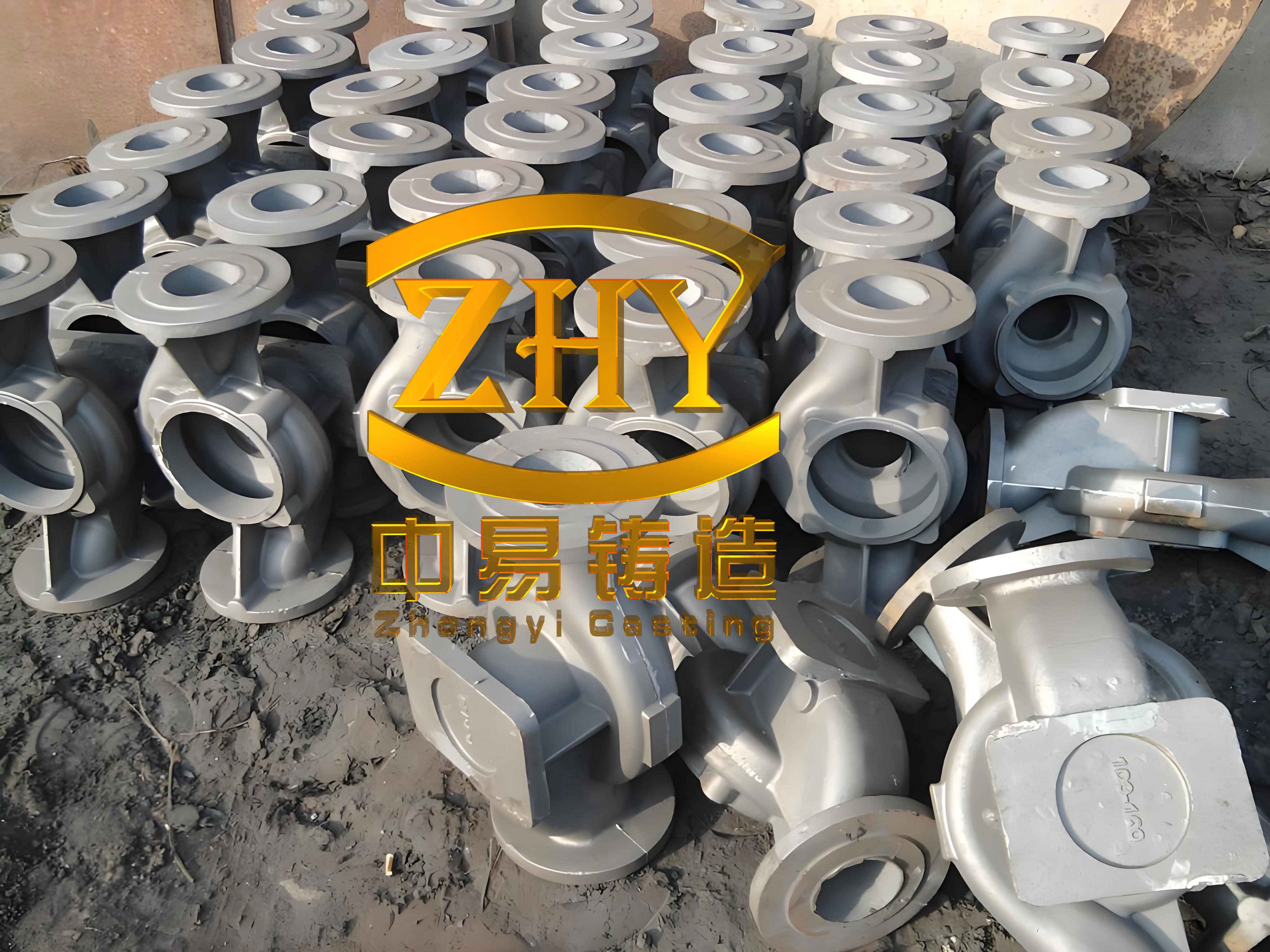
To understand the root causes, let’s delve into the solidification dynamics of grey iron casting. Grey iron exhibits a unique solidification behavior due to graphite precipitation, which can offset shrinkage through expansion. However, in heavy sections, the prolonged solidification time can overwhelm this expansion, leading to macro-shrinkage if feeding is inadequate. The feeding requirement can be approximated using the modulus method, where the modulus \( M \) is defined as the volume-to-surface area ratio:
$$ M = \frac{V}{A} $$
For a plate-like section of thickness \( T \), the modulus simplifies to \( M \approx T/2 \). In our grey iron casting, the base face has a modulus of approximately 125 mm, while thin sections are around 15 mm. This disparity necessitates careful thermal management to ensure directional solidification toward feeders. The solidification time \( t \) can be estimated using Chvorinov’s rule:
$$ t = k \cdot M^n $$
where \( k \) is a mold constant and \( n \) is an exponent typically around 2. For thick-section grey iron casting, \( t \) can be excessively long, promoting coarse graphite formation and shrinkage.
Initially, the production process employed resin sand hand molding. The parting line was set at the top of the thick base face, placing the entire casting in the cope and the thick machining face at the bottom. This orientation aimed to ensure quality on critical machined surfaces (inner bore and bearing faces) but inadvertently hindered feeding. A closed gating system with ratios \( F_{\text{sprue}}: F_{\text{runner}}: F_{\text{ingate}} = 1: 1.8: 0.85 \) was used, with side gating from top and bottom. Chills were placed on the thick face, and duck-bill risers were positioned on the top. The molten metal composition and pouring temperature are summarized in Table 1.
| Element/Parameter | Value (wt.%) | Role in Grey Iron Casting |
|---|---|---|
| Carbon (C) | 3.10 | Promotes graphite formation, affects fluidity and shrinkage |
| Silicon (Si) | 1.68 | Graphitizer, influences matrix structure |
| Manganese (Mn) | 0.86 | Strengthens pearlite, counteracts sulfur |
| Phosphorus (P) | 0.028 | Typically kept low to avoid brittleness |
| Sulfur (S) | 0.007 | Low to prevent chill and shrinkage |
| Copper (Cu) | 0.45 | Enhances strength and corrosion resistance |
| Carbon Equivalent (CE) | 3.66 | CE = C + 0.33(Si + P), indicates castability |
| Pouring Temperature | 1320–1340°C | High to ensure fluidity but increases shrinkage risk |
Despite these measures, out of six castings produced, four exhibited concentrated shrinkage cavities and cracks at the riser roots and adjacent areas, leading to scrap. Analysis revealed two primary issues: first, the thick face was at the bottom, far from the top risers, resulting in insufficient液态补缩 during late solidification. Second, the sprue was too close to the casting, causing localized overheating and delayed solidification. This highlighted the need for a holistic redesign focusing on feeding and thermal control in grey iron casting.
To mitigate these defects, I spearheaded a comprehensive工艺改进. The key changes were as follows:
- Reorientation of Casting: The parting line remained unchanged, but the thick machining face was moved to the top of the mold. This leverages gravity to promote directional solidification from thin sections (bottom) to thick sections (top), facilitating riser feeding. The bearing faces were placed on the side.
- Gating System Modification: The sprue was distanced 200 mm from the casting to reduce thermal influence. The gating ratios were adjusted to \( F_{\text{sprue}}: F_{\text{runner}}: F_{\text{ingate}} = 1: 1.5: 0.85 \), with gating from the bearing face side to ensure平稳 filling.
- Enhanced Cooling: Direct chills over 120 mm thick were applied on the top thick face to accelerate cooling, reduce shrinkage tendency, and prevent coarse graphite—a common issue in heavy-section grey iron casting.
- Riser Optimization: Duck-bill risers were relocated to avoid the hottest spots of the casting, minimizing thermal junctions at riser necks. This prevents localized shrinkage.
- Temperature and Composition Adjustment: Lowering the pouring temperature to 1300–1320°C reduces液态收缩 while maintaining fluidity, as thin sections fill first. The composition was tweaked to increase graphitization potential: CE raised to 3.85% and Cu to 0.58% to enhance strength without exacerbating shrinkage.
The new parameters are summarized in Table 2, along with their theoretical basis.
| Parameter | Optimized Value | Rationale |
|---|---|---|
| Pouring Position | Thick face up | Enables directional solidification, improves feeding |
| Sprue Distance | 200 mm | Minimizes thermal impact on casting |
| Gating Ratio (F_s:F_r:F_i) | 1:1.5:0.85 | Balances flow and reduces turbulence |
| Chill Thickness | >120 mm | Increases cooling rate, refines microstructure |
| Riser Type | Duck-bill + Edge risers | Avoids hot spots, provides adequate feed metal |
| Pouring Temperature | 1300–1320°C | Lowers液态收缩, maintains fillability |
| Carbon Equivalent (CE) | 3.85% | Enhances graphite expansion to counteract shrinkage |
| Copper Content | 0.58% | Boosts strength without increasing shrinkage tendency |
To validate these changes, I employed MAGMA simulation software to model solidification and feeding. The initial改进方案 showed promising results, but simulations indicated that the central duck-bill risers still posed a risk due to large thermal junctions. The feeding efficiency of a riser in grey iron casting can be assessed by the feeding modulus \( M_f \), which should satisfy:
$$ M_f \geq \frac{M_c \cdot \alpha}{\beta} $$
where \( M_c \) is the casting modulus, \( \alpha \) is the shrinkage factor, and \( \beta \) is the feeding efficiency factor. For grey iron casting, \( \alpha \) is typically 0.5–1.5% depending on composition, and \( \beta \) ranges 0.1–0.3 for side risers. Simulation revealed that replacing central risers with an edge riser on the far side from the sprue would provide sufficient feed while avoiding hot spots. The final design, shown in Figure 1, uses a combination of chills, duck-bill risers with reduced neck dimensions, and an edge riser.
The simulation results confirmed a sound casting with no shrinkage defects. The solidification sequence showed progressive cooling from thin to thick sections, with the edge riser solidifying last, ensuring adequate feeding. The temperature distribution \( T(x,y,z,t) \) during solidification can be modeled using the heat conduction equation:
$$ \rho c_p \frac{\partial T}{\partial t} = \nabla \cdot (k \nabla T) + \dot{q} $$
where \( \rho \) is density, \( c_p \) is specific heat, \( k \) is thermal conductivity, and \( \dot{q} \) is latent heat release from graphite precipitation. For grey iron casting, the latent heat significantly affects cooling curves, and the simulation accounted for this.
Upon implementation, the first two castings were produced flawlessly. A batch of 30 units followed with zero scrap, demonstrating the robustness of the optimized process. Machining revealed no defects, and the mechanical properties met HT300 specifications. Table 3 summarizes the quality metrics of the improved grey iron casting.
| Property | Result | Standard (HT300) |
|---|---|---|
| Tensile Strength (附铸试块) | 320 MPa | >300 MPa |
| Hardness (HB) | 180 | 170–220 |
| Graphite Morphology | Type A | A-type preferred |
| Graphite Length | Grade 5 | Fine to medium |
| Pearlite Content | 85% | >80% |
| Defect Incidence | 0% | None allowed |
The success of this project underscores several principles for heavy-section grey iron casting. Firstly,浇注位置 must prioritize feeding dynamics over mere convenience; placing thick sections at the top exploits gravity for补缩. Secondly, riser design should avoid thermal junctions—using edge risers or carefully sized necks can prevent shrinkage at riser roots. Thirdly, chills are indispensable for thick-section grey iron casting to accelerate cooling and refine microstructure. Fourthly, simulation tools like MAGMA are invaluable for predicting defects and optimizing工艺参数. Lastly, a synergistic approach combining工艺改进 and melt composition adjustments is key; for instance, raising CE enhances graphite expansion, which can compensate for shrinkage in grey iron casting.
From a broader perspective, this case highlights the interplay between geometry, thermodynamics, and material science in grey iron casting. The solidification of grey iron involves complex phase transformations, described by equations like:
$$ \frac{dG}{dt} = k_g (C_e – C)^m $$
where \( G \) is graphite growth, \( k_g \) is a kinetic constant, \( C_e \) is equilibrium carbon concentration, \( C \) is actual concentration, and \( m \) is an exponent. In thick sections, slow cooling leads to larger \( G \), hence coarse graphite. By using chills and controlled cooling, we mitigate this.
In conclusion, tackling shrinkage in heavy-section grey iron casting requires a multifaceted strategy. My experience with this bearing housing shows that by reorienting the casting, optimizing gating and risering, employing chills, and fine-tuning composition, defect-free production is achievable. These lessons can be extrapolated to other challenging grey iron casting projects, ensuring reliability in critical applications. As grey iron casting continues to evolve, embracing simulation and holistic工艺设计 will be paramount for advancing the foundry industry.