
1. Typing scheme
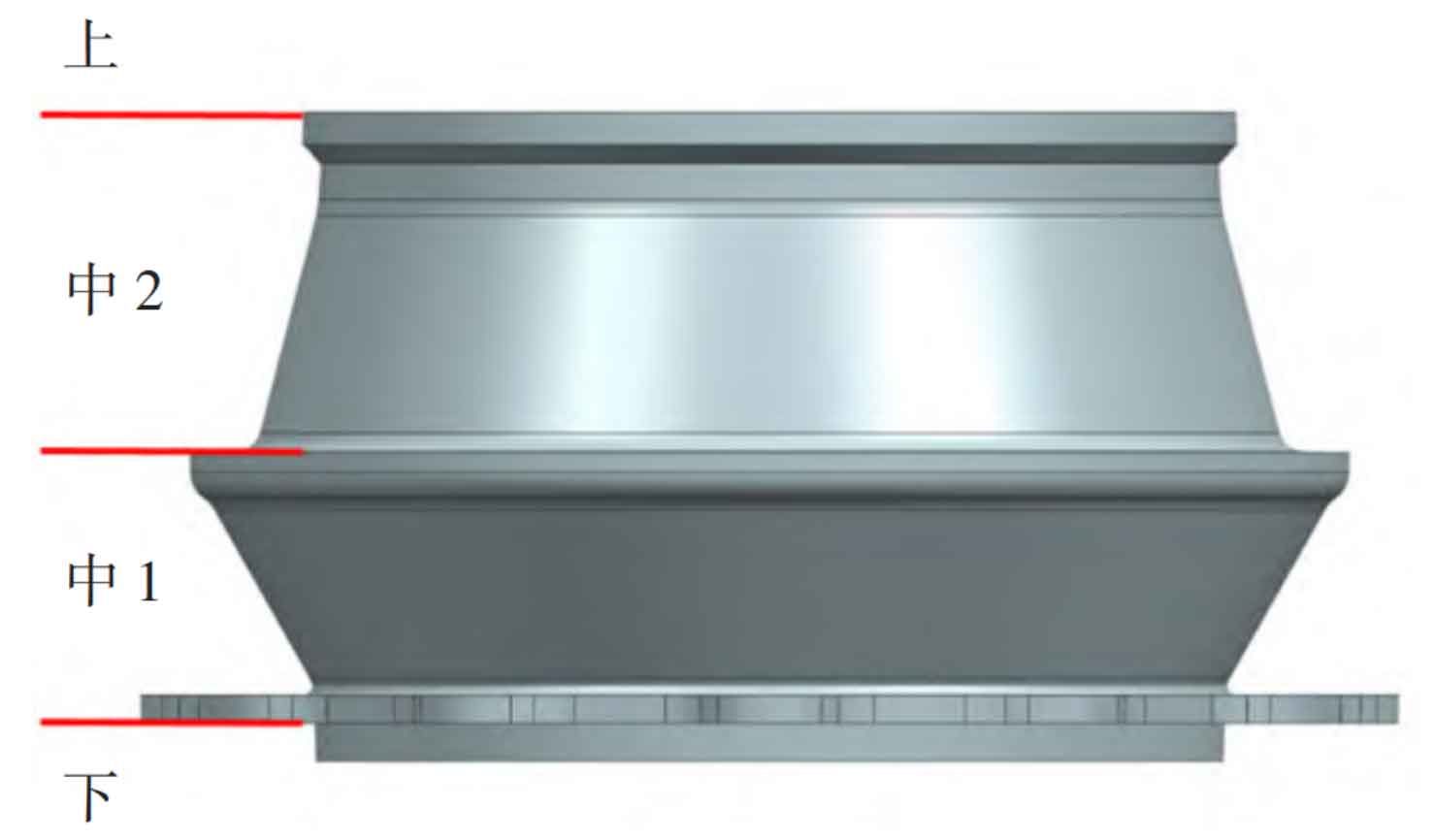
The parting scheme is that the motor hole flange is facing down, and the parting is carried out from the lower part of the motor hole flange. The main body of the nodular cast iron is placed on the upper part. The four-box molding scheme is adopted. The box is divided at the rotor connecting flange, and then at the top bearing flange. The shape is a whole movable block. The inner cavity structure is taken out by the large core as a whole, and the core head is set at the bottom side of the large core for positioning, and the pouring system is arranged at the bottom of the large core, Because the outer contour and key dimensions of ductile iron castings are formed by sand mold, the core assembly times are small and the operation is simple, the overall dimension can be controlled at a high precision level. The parting scheme is shown in Figure 1.
2. Design of gating system
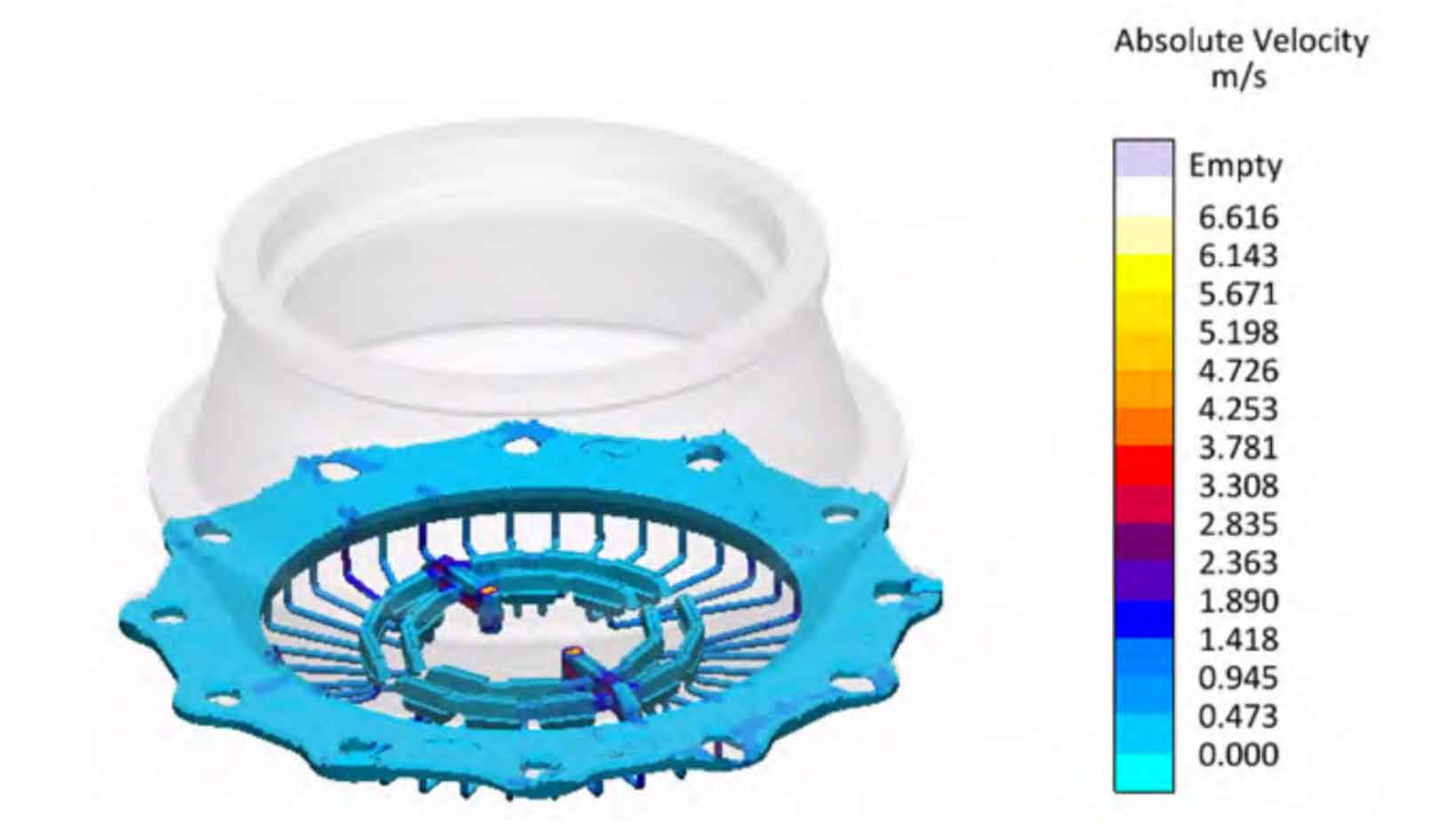
The open gating system is used to feed from the end face of the bottom flange of the ductile iron casting. The pouring time is 160 seconds. The gating system proportion Σ F straight: Σ F horizontal: Σ F internal=1:1.8:5. The flow rate of the runner is controlled within 0.5 m/s. The molten iron is rectified and filtered with a high-efficiency filter screen made of zirconia and with a unit pore density of 10 ppi. The diameter of the sprue is reduced from top to bottom, and the transverse sprue is located under the ductile iron castings as a whole, so as to realize the rapid filling of the gating system, the stable filling of molten iron, the suppression of turbulence and splash, and the effective reduction of secondary oxidation slag. The large open proportion gating system often has the problem of large sectional area of the inner runner. Therefore, the variable diameter flat ceramic runner is used to change the inner runner into a flat wide shape, reduce the contact hot spot at the connection between the inner runner and the ductile iron casting, and thus reduce the shrinkage tendency of the inner runner position. Try to make the inner runner uniformly distributed and flow at the same time to make the temperature field uniform. Figure 2 shows the simulation diagram of the flow rate in the filling process.
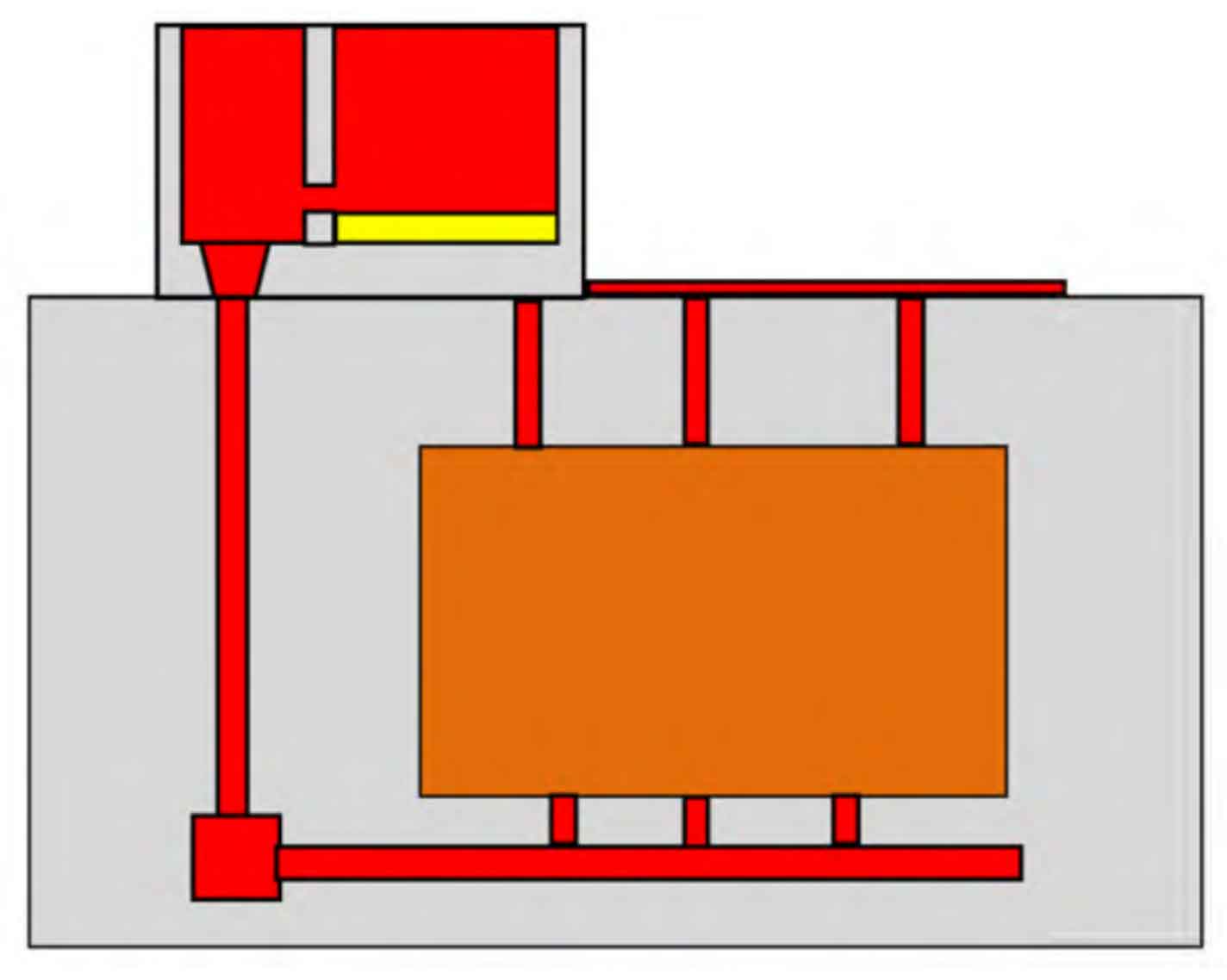
In addition, the capacity of the pouring cup should be able to hold 50% of the total molten iron mass, and ensure that the molten iron stays in the pouring cup for 30~60 s, so that the slag can fully float above the liquid level. The bottom of the pouring cup should be equipped with a slag retaining dam to prevent the dirty molten iron at the top of the liquid level from entering the mold cavity in the later stage. Figure 3 is the schematic diagram of the slag retaining pouring cup.
3. Design of feeding system
The graphite core of spheroidal graphite cast iron eutectic cluster is grown under the surrounding of austenite. The volume expansion generated by the growth of graphite spheroid is effected by the expansion of austenite. Only a small part of this expansion is transferred to the liquid iron between dendrites, while most of it acts on the adjacent eutectic cluster or primary austenite skeleton. In addition, spheroidal graphite cast iron is “paste solidification”, and its shell is not solid enough during the whole solidification period, In the case of insufficient mold rigidity, the liquid shrinkage and solidification shrinkage of the internal liquid between dendrites or eutectic clusters can not be compensated, so the ductile iron is prone to shrinkage defects. It is necessary to control the process design, metallurgical quality and mold rigidity, among which the design of chill and riser is particularly critical.
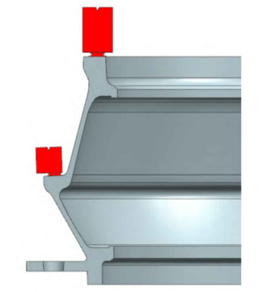
First, calculate the modulus and volume of feeding liquid of ductile iron castings, then determine the position and size of the riser in combination with the feeding distance and efficiency of the riser, use the cold iron reasonably to eliminate local hot spots, adjust the cooling speed and temperature gradient of the ductile iron castings, place the riser at the final solidification position to realize compensation for liquid shrinkage, and ensure that the riser is later than the ductile iron castings to solidify, so that the ductile iron castings tend to solidify in sequence. Its modulus ratio is approximately M riser neck=1.1M ductile iron castings, M riser=1.2M riser neck. During the actual production of this nodular cast iron, two rings of insulation heating risers are distributed on the top surface of the casting and the connecting flange of the rotor, as shown in Figure 4.