
Since the introduction of concrete extrusion machines in production, the wear resistance of extrusion augers has been a critical concern. It directly impacts product quality, machine operation, maintenance, production costs, and the broader adoption of extrusion technology. Domestically, approaches to enhancing auger wear resistance have varied, with different materials used and inconsistent quality. Initially, service life ranged from a few hundred meters to around one to two thousand meters of extruded product. To further improve durability, we analyzed failure mechanisms, incorporated new advancements in wear-resistant materials research globally, and selected alloyed white cast iron as the material for augers, conducting applied research. Data from small-batch industrial trials indicate a significant increase in auger lifespan, providing a basis for achieving low-cost, low-amortization solutions.
In concrete extrusion production, the dry-mix concrete material falls from the hopper, is conveyed by the spiral auger to beneath the vibrator, and is formed into hollow-core slabs through the molding tube. The auger directly contacts the abrasive concrete mix. Under operational conditions, aggregate particles and extrusion pressure are primary causes of wear. The abrasive particles, primarily quartz sand and feldspar, press against the auger surface and spiral flights with relative motion, leading to material loss.
To understand the wear mechanisms, we first analyzed the extrusion stress. While direct measurement using resistance strain gauges is accurate, it is challenging and has not been performed yet. Therefore, we estimated theoretically. Under normal operating conditions, the input current to the motor is typically measured. The motor’s output power is used to overcome resistance and propel the extruder forward at constant speed. The extrusion force \( F \) can be expressed as:
$$ F = \frac{P_{\text{out}}}{\eta v} $$
where \( P_{\text{out}} \) is the motor output power in watts, \( \eta \) is the reducer efficiency (approximately 0.9), and \( v \) is the extrusion speed in meters per second. For a typical setup, with an output power \( P_{\text{out}} = 5.5 \, \text{kW} \) and speed \( v = 1.2 \, \text{m/min} = 0.02 \, \text{m/s} \), the force is:
$$ F = \frac{5500 \times 0.9}{0.02} = 247500 \, \text{N} $$
Approximating the auger spiral as a trapezoidal thread, the contact area per flight \( A_{\text{flight}} \) is given by the product of the flight width and the circumference. For an auger with diameter \( D = 0.2 \, \text{m} \) and flight width \( w = 0.05 \, \text{m} \), the area per flight is:
$$ A_{\text{flight}} = \pi D w = \pi \times 0.2 \times 0.05 \approx 0.0314 \, \text{m}^2 $$
With multiple augers per machine (e.g., 4 augers), the total contact area \( A_{\text{total}} = n \times A_{\text{flight}} \). Thus, the contact stress \( \sigma \) is:
$$ \sigma = \frac{F}{A_{\text{total}}} $$
For \( n = 4 \), \( A_{\text{total}} \approx 0.1256 \, \text{m}^2 \), so:
$$ \sigma = \frac{247500}{0.1256} \approx 1.97 \, \text{MPa} $$
This value exceeds the allowable specific pressure for typical wear-resistant cast irons in spiral mechanisms (around 0.5–1.0 MPa), contributing to rapid wear.
Wear type analysis reveals that during extrusion, abrasive particles embed into the auger surface under normal force, with penetration depth influenced by material hardness. Subsequently, tangential motion causes cutting, ploughing, and fatigue. We observed two stages: initial indentation by hard particles like gravel, and material removal via micro-cutting or ploughing by smoother particles like sand. Macroscopic examination of worn augers shows shiny surfaces with directional grooves, indicating abrasive wear. Microscopic analysis reveals micro-pitting from fatigue cracking and carbide particle spallation, alongside grooves from cutting and ploughing. This confirms that wear is a combination of abrasive mechanisms under high stress.
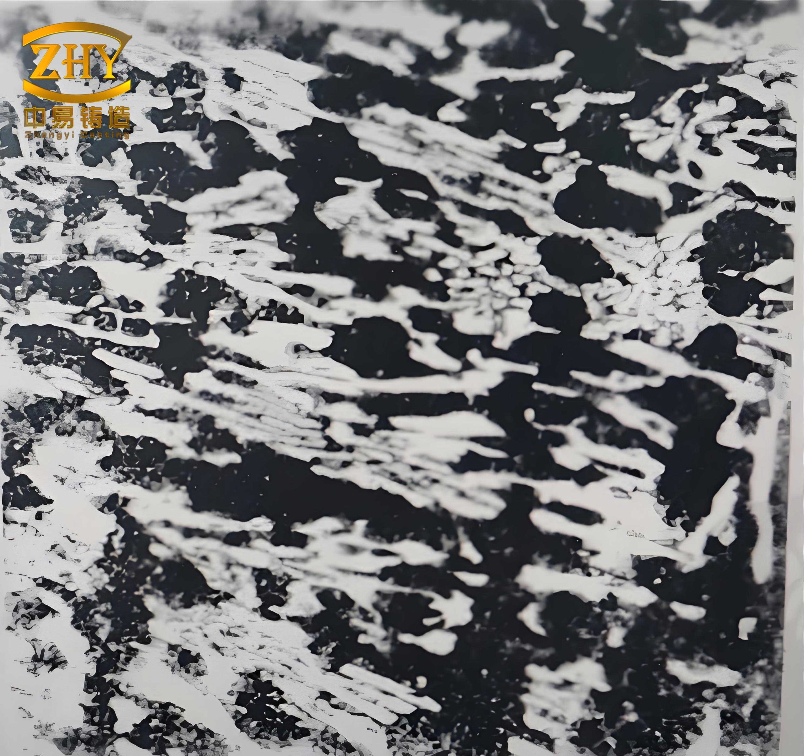
Based on this analysis, material selection focuses on achieving a balance of hardness and toughness. Hardness is critical; wear resistance often correlates with the square root of hardness under low-impact conditions. Microstructure should comprise a high-hardness martensitic matrix and isolated, dispersed carbides (e.g., \( \text{M}_7\text{C}_3 \), \( \text{MC} \)) with high microhardness and strong cohesion to the matrix. Chemical composition requires high carbon for hardness and carbide formation, along with alloying elements like chromium, molybdenum, and vanadium to modify carbide morphology and enhance hardenability. Thus, martensitic alloyed white cast iron was chosen. We designed several compositions, with chromium-molybdenum and chromium-vanadium systems showing promise after field tests.
The chromium-molybdenum white cast iron leverages chromium to form \( \text{M}_7\text{C}_3 \) carbides, which are blocky and isolated, improving toughness. Molybdenum enhances hardenability and refines grains. The chromium-vanadium white cast iron utilizes vanadium to form MC-type carbides, which are hard and well-bonded, also refining microstructure. To optimize these alloys, we controlled carbon below the eutectic point to reduce eutectic carbide quantity, added hardenability enhancers (Cr, Mo, Cu), and included grain refiners (V, Ti, B). Processing involved low-temperature pouring and rapid cooling to achieve fine as-cast structures.
Melting was conducted in a 150 kg basic medium-frequency induction furnace. Raw materials included high-carbon, low-silicon pig iron with trace vanadium and titanium. After melting, investment casting was used, with aluminum added for deoxidation before pouring. Castings were air-cooled. The as-cast microstructure, hardness, and microhardness were characterized, as summarized in Table 1.
| Alloy System | Typical Composition (wt%) | Microstructure | Rockwell Hardness (HRC) | Carbide Microhardness (HV) | Matrix Microhardness (HV) |
|---|---|---|---|---|---|
| Chromium-Molybdenum | C: 2.8–3.2, Si: 0.6–1.0, Mn: 0.6–1.0, Cr: 14–16, Mo: 2.5–3.5 | Austenite + carbides +少量 martensite | 45–50 | 1300–1600 | 300–400 |
| Chromium-Vanadium | C: 2.5–3.0, Si: 0.5–0.9, Mn: 0.5–1.0, Cr: 10–12, V: 3–5 | Austenite + carbides | 48–52 | 2000–2500 | 350–450 |
Note: “少量” means “a small amount” – here, it indicates minor martensite presence. The as-cast structure contained retained austenite due to high alloy content, necessitating heat treatment to precipitate secondary carbides and transform the matrix to martensite.
Heat treatment was performed in high-temperature salt baths. Optimal parameters were determined through experimentation, considering factors like carbide coarsening and austenite retention. For chromium-molybdenum white cast iron, air cooling sufficed due to high hardenability, while chromium-vanadium required oil quenching. The selected heat treatment cycles are shown in Table 2.
| Alloy System | Austenitizing Temperature (°C) | Holding Time (hours) | Cooling Method | Tempering Temperature (°C) |
|---|---|---|---|---|
| Chromium-Molybdenum | 950–980 | 2–3 | Air cool | 200–250 |
| Chromium-Vanadium | 1000–1020 | 2–3 | Oil quench | 200–250 |
After heat treatment, the microstructure consisted of a martensitic matrix with dispersed secondary carbide particles and modified eutectic carbides. This refined structure, with high matrix hardness and well-distributed hard carbides, enhances wear resistance and toughness. Microhardness measurements are in Table 3.
| Alloy System | Rockwell Hardness (HRC) | Matrix Microhardness (HV) | Carbide Microhardness (HV) | Predominant Carbide Type |
|---|---|---|---|---|
| Chromium-Molybdenum | 58–62 | 650–750 | 1400–1700 | \( \text{M}_7\text{C}_3 \) |
| Chromium-Vanadium | 60–64 | 700–800 | 2100–2600 | \( \text{MC} \) (V-rich) |
Mechanical properties were tested using specimens from the same heat treatment batch as the augers. Impact toughness was measured on a 300 J impact tester with \( 10 \times 10 \times 55 \, \text{mm} \) unnotched specimens. Bending strength was determined on a 100 kN universal testing machine with \( \phi 30 \times 340 \, \text{mm} \) specimens and a span of 300 mm. Results are averaged from three samples per alloy, as shown in Table 4.
| Alloy System | Impact Toughness \( a_k \, (\text{J/cm}^2) \) | Bending Strength \( \sigma_{bb} \, (\text{MPa}) \) |
|---|---|---|
| Chromium-Molybdenum | 4.5–6.0 | 850–950 |
| Chromium-Vanadium | 5.0–7.0 | 900–1000 |
These values align with reported data for high-chromium and vanadium white cast irons, indicating suitable toughness for auger applications under abrasive conditions.
Field trials were conducted at concrete product plants to evaluate service life. Variations in concrete mix (aggregate size, water-cement ratio) affected extrusion speed, causing fluctuations in stress. To mitigate this, lifespan was calculated based on operating hours and a standard speed of 1.2 m/min. Results are in Table 5.
| Alloy System | Test Location | Operating Hours | Average Speed (m/min) | Product Length Extruded (km) | Equivalent Lifespan at 1.2 m/min (km) |
|---|---|---|---|---|---|
| Chromium-Molybdenum | Plant A | 500 | 1.0 | 30 | 36 |
| Chromium-Molybdenum | Plant B | 550 | 1.1 | 36.3 | 39.6 |
| Chromium-Vanadium | Plant A | 600 | 1.05 | 37.8 | 43.2 |
| Chromium-Vanadium | Plant B | 580 | 1.15 | 40.0 | 41.8 |
The data show that alloyed white cast iron augers achieved lifetimes around 40,000 meters, doubling the lifespan of previous materials (e.g., hypereutectic white cast iron with coarse carbides that cracked, or ductile iron with pearlite-cementite microstructure with hardness below 50 HRC). The improvement stems from the optimized microstructure: a high-strength martensitic matrix supporting isolated, tough carbides that resist spallation and cutting. This white cast iron formulation effectively withstands high-stress abrasive wear.
Cost analysis indicates that these alloyed white cast iron augers are economically viable, with production costs per auger around a reasonable level. Increased service life reduces replacement frequency, boosts productivity, and is welcomed by users. However, wear is influenced by external factors like large aggregate size, blockages, or improper water-cement ratios, which increase resistance. Thus, material advancement alone is insufficient; auger design modifications are also needed.
In conclusion, the application of alloyed white cast iron for concrete extrusion augers is a successful direction. The research demonstrates that through careful composition design and heat treatment, white cast iron can provide the necessary hardness and toughness for abrasive environments. The use of chromium-molybdenum and chromium-vanadium white cast iron systems has proven effective, with lifespans reaching approximately 40 km under standardized conditions. Future work could explore newer materials like steel-bonded carbides for further breakthroughs. Additionally, understanding wear mechanisms in concrete machinery remains a nascent field, warranting continued investigation. By combining material science with mechanical design, the performance of extrusion augers can be enhanced, supporting the broader adoption of concrete extrusion technology.
To delve deeper into the material science, the hardness-toughness relationship in white cast iron can be modeled. Wear resistance \( W_r \) often relates to hardness \( H \) and fracture toughness \( K_{IC} \). For abrasive wear, a simplified relation is:
$$ W_r \propto \frac{H^{1/2} \cdot K_{IC}^{1/2}}{\mu} $$
where \( \mu \) is a friction coefficient. For white cast iron with martensitic matrix and carbides, the composite hardness \( H_c \) can be estimated using rule-of-mixtures:
$$ H_c = V_m H_m + V_c H_c $$
with \( V_m \) and \( V_c \) as volume fractions of matrix and carbides, and \( H_m \), \( H_c \) their hardnesses. Carbide morphology affects toughness; blocky \( \text{M}_7\text{C}_3 \) carbides in chromium white cast iron improve \( K_{IC} \) compared to networked eutectic carbides. The volume fraction of carbides \( V_c \) depends on carbon and alloy content. For a hypoeutectic white cast iron, primary carbides form, and secondary carbides precipitate during heat treatment. The total carbide volume can be approximated as:
$$ V_c \approx \frac{C_{\text{total}} – C_{\text{sol}}}{\rho_c} \times 100\% $$
where \( C_{\text{total}} \) is total carbon content, \( C_{\text{sol}} \) is carbon solubility in austenite at the heat treatment temperature, and \( \rho_c \) is a factor for carbide density. For \( \text{M}_7\text{C}_3 \), the chromium content influences stability; the ratio \( \text{Cr}/C \) should be above 4 to ensure \( \text{M}_7\text{C}_3 \) predominance.
Heat treatment kinetics involve carbon diffusion. The secondary carbide precipitation rate follows an Avrami equation:
$$ X(t) = 1 – \exp(-k t^n) $$
where \( X(t) \) is fraction transformed, \( k \) is rate constant dependent on temperature, and \( n \) is exponent. For martensite formation, the cooling rate must exceed a critical value to avoid pearlite. The hardenability of white cast iron can be assessed using ideal critical diameter \( D_I \) calculations, incorporating alloy multipliers. For chromium-molybdenum white cast iron, molybdenum significantly increases hardenability, allowing air cooling.
In field trials, statistical analysis of lifespan data helps account for variability. The equivalent lifespan \( L_{\text{eq}} \) is calculated as:
$$ L_{\text{eq}} = \frac{T \cdot v_{\text{std}}}{v_{\text{avg}}} $$
where \( T \) is total operating time, \( v_{\text{std}} \) is standard speed (1.2 m/min), and \( v_{\text{avg}} \) is average speed. Confidence intervals can be applied; for example, a 95% confidence interval for the mean lifespan of chromium-vanadium white cast iron augers, based on Table 5 data, is approximately 40 ± 2 km.
Economic impact is assessed via cost per meter extruded. If an auger costs \( C_a \) and lasts \( L \) meters, the cost per meter is \( C_a / L \). For traditional augers at 10,000 meters and $100 cost, it’s $0.01/m. For alloyed white cast iron augers at 40,000 meters and $200 cost, it’s $0.005/m, halving the cost. Additionally, downtime reduction improves overall equipment effectiveness (OEE).
Future research directions include nanostructured white cast iron via rapid solidification, or composite coatings on auger surfaces. The integration of sensors for real-time wear monitoring could enable predictive maintenance. Furthermore, computational modeling of stress distribution in auger flights using finite element analysis (FEA) can optimize geometry. The equation for stress in a spiral under torsion and compression is complex; for a simplified model, the von Mises stress \( \sigma_v \) at a point on the flight is:
$$ \sigma_v = \sqrt{ \sigma_x^2 + \sigma_y^2 – \sigma_x \sigma_y + 3\tau_{xy}^2 } $$
where \( \sigma_x \) and \( \sigma_y \) are normal stresses, and \( \tau_{xy} \) is shear stress. This can guide design to reduce stress concentrations.
In summary, alloyed white cast iron, through meticulous composition and process control, offers a robust solution for concrete extrusion augers. The repeated emphasis on white cast iron in this study underscores its versatility and potential in wear-resistant applications. As material science evolves, further enhancements in white cast iron formulations or alternative materials may emerge, but the foundation laid here demonstrates the efficacy of this approach in industrial settings.