
In my experience as a casting process engineer, working with nodular cast iron presents unique challenges and opportunities due to its excellent mechanical properties, such as high strength and ductility. This article details my firsthand approach to developing a casting process for a large-scale intercooler seat tube made from nodular cast iron, specifically QT500-7 grade. The component is critical for diesel engine applications, integrating air intake and water inlet functions, and falls under the category of thin-walled box-type castings. Throughout this study, I emphasize the importance of meticulous design to meet stringent quality standards, leveraging tables and formulas to summarize key aspects. The term ‘nodular cast iron’ will be frequently referenced to underscore its centrality in this work.
The intercooler seat tube has an overall dimension of 2154 mm × 506 mm × 232 mm and weighs approximately 235 kg in the as-cast state. Its primary wall thickness is 10 mm, with flanges on the back featuring uniformly distributed bosses of 50 mm in diameter and 50 mm in height, leading to significant wall thickness variations. The tolerance for wall thickness is critically tight at ±0.405 mm. Below is a table summarizing the key structural parameters:
| Parameter | Value | Unit |
|---|---|---|
| Length | 2154 | mm |
| Width | 506 | mm |
| Height | 232 | mm |
| As-cast Weight | 235 | kg |
| Primary Wall Thickness | 10 | mm |
| Wall Thickness Tolerance | ±0.405 | mm |
| Boss Dimensions | Ø50 × 50 | mm |
Quality requirements for this nodular cast iron casting are rigorous. First, after machining, the component must undergo a hydrostatic pressure test where the internal cavity and side pipelines maintain a pressure of 0.5 MPa for at least 5 minutes without any leakage. Machined surfaces must be free from defects like porosity, shrinkage cavities, or shrinkage porosity. Second, surface quality is paramount: no sand sticking, iron penetration, or similar defects are allowed. The internal cavity must have smooth transitions, and after shot blasting, both inner and outer walls must achieve a specified surface roughness. Third, dimensional accuracy is crucial, with all wall thicknesses inspected to stay within tolerance. The finished weight is required to be 225 kg with a tolerance of 5%. I summarize these requirements in the following table:
| Requirement Category | Specification |
|---|---|
| Hydrostatic Test | 0.5 MPa for 5 min, no leakage |
| Surface Defects | No porosity, shrinkage, sand sticking, or iron penetration |
| Surface Roughness | Must meet spec after shot blasting |
| Dimensional Accuracy | Wall thickness within ±0.405 mm |
| Weight Tolerance | 225 kg ± 5% |
To meet these demands, I focused on optimizing the casting process for nodular cast iron. The initial step involved determining the molding process. Given the complex geometry, I adopted a two-box core assembly method. Instead of a traditional three-box setup, I expanded the side lower core to cover the top surface of the casting, simplifying operations. The pattern for the lower mold was designed only up to the water pipe centerline. After placing all cores in the lower mold, an intermediate flask was set around them, and sand was compacted behind the cores. This approach not only streamlined molding but also reduced tooling costs, which is vital for nodular cast iron applications where precision is key.
The gating system design was critical for ensuring sound nodular cast iron castings. I implemented a bottom-up gating system located within the large internal bore of the casting. This configuration offers several advantages: it maintains a full cross-section in the runners during pouring, even with intermittent flow, effectively trapping slag and preventing slag inclusions; it allows metal to enter the mold cavity smoothly from the bottom, minimizing turbulence, oxidation, and cold shuts; and it shortens the flow distance within the mold, reducing defects like cold laps. The area ratios of the gating system were carefully calculated. For nodular cast iron, the relationship is often expressed as:
$$ \sum F_{\text{sprue}} : \sum F_{\text{runner}} : \sum F_{\text{ingate}} = 1 : 1.85 : 1.19 $$
where $\sum F_{\text{sprue}}$ is the total cross-sectional area of the sprue, $\sum F_{\text{runner}}$ for the runner, and $\sum F_{\text{ingate}}$ for the ingates. This ratio ensures proper flow characteristics for nodular cast iron, minimizing velocity and promoting laminar filling. The design can be summarized in the table below:
| Gating Component | Cross-Sectional Area Ratio | Function |
|---|---|---|
| Sprue | 1.00 | Initial metal delivery |
| Runner | 1.85 | Distributes metal and traps slag |
| Ingates | 1.19 | Controls entry into cavity |
Core design and anti-error features were essential for this nodular cast iron casting. Since core assembly is involved, I added interlocking定位 between upper and lower core layers to ensure accuracy. The four side补砂 cores interfered with the water pipe cores during placement, so I offset their seats by 20 mm outward, allowing them to be set and fixed with sand afterward. To prevent misplacement of similar-looking cores, I incorporated distinct anti-error定位 devices—each core has a unique shape or key that prevents incorrect assembly. This is crucial for nodular cast iron castings, where core shifts can lead to dimensional inaccuracies and scrap.
Chill and core support design played a vital role in managing solidification. For nodular cast iron, which has a tendency for shrinkage due to its graphite formation, I modified the core supports to have a 2 mm thick iron片 that matches the outer contour of the cores. This enhances stability against buoyancy forces from the molten metal. The formula for buoyancy force $F_b$ can be expressed as:
$$ F_b = \rho_{\text{iron}} \cdot g \cdot V_{\text{displaced}} $$
where $\rho_{\text{iron}}$ is the density of nodular cast iron (approximately 7100 kg/m³), $g$ is gravity (9.81 m/s²), and $V_{\text{displaced}}$ is the volume of the core submerged. By increasing support area, I reduced the risk of core floating. Additionally, I placed chills at the thick boss sections to accelerate cooling and balance solidification rates. The effectiveness of chills can be approximated using the Chvorinov’s rule for solidification time $t$:
$$ t = k \left( \frac{V}{A} \right)^2 $$
where $V$ is volume, $A$ is surface area, and $k$ is a constant dependent on the material and mold properties. For nodular cast iron, introducing chills increases the effective surface area $A$, reducing $t$ at hot spots and minimizing shrinkage defects. I summarize the chill placement strategy in the table below:
| Location | Chill Type | Purpose |
|---|---|---|
| Boss areas (Ø50 mm) | Steel chills | Accelerate solidification, prevent shrinkage |
| Core supports | Contoured iron片 | Stabilize cores against buoyancy |
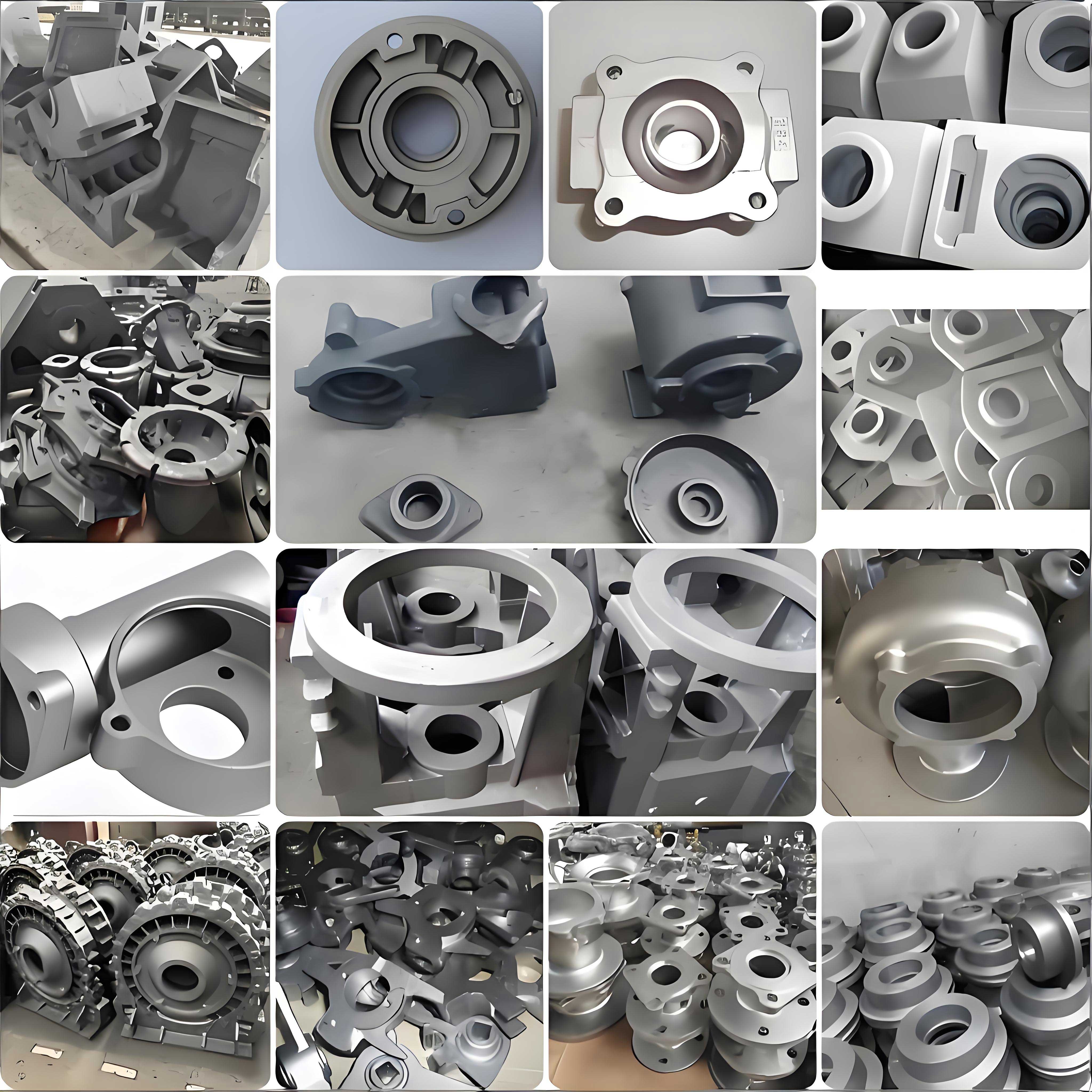
The implementation of this process for nodular cast iron yielded significant improvements. Defect rates for slag inclusions and cold shuts were virtually eliminated. After machining and hydrostatic testing, the occurrence of shrinkage porosity and leaks was drastically reduced, with a reject rate controlled below 3%. The simplified two-box molding reduced labor and improved dimensional consistency. To visualize a typical nodular cast iron casting process, I include an image that illustrates key aspects:
Further analysis involved modeling the solidification behavior of nodular cast iron. The cooling curve for nodular cast iron can be described using the Fourier heat conduction equation:
$$ \frac{\partial T}{\partial t} = \alpha \nabla^2 T $$
where $T$ is temperature, $t$ is time, and $\alpha$ is thermal diffusivity. For QT500-7 nodular cast iron, $\alpha$ is approximately 1.2 × 10⁻⁵ m²/s. By simulating this, I optimized chill sizes and locations. Additionally, the gating system design was validated through fluid flow simulations, ensuring minimal turbulence for nodular cast iron. The Reynolds number $Re$ for flow in the ingates was kept low:
$$ Re = \frac{\rho v D}{\mu} $$
where $v$ is velocity, $D$ is hydraulic diameter, and $\mu$ is viscosity. For nodular cast iron, maintaining $Re < 2000$ helps avoid turbulent entry.
Material properties of nodular cast iron also influenced process decisions. The QT500-7 grade has a tensile strength of 500 MPa and elongation of 7%, which requires controlled cooling to achieve desired microstructure. The solidification shrinkage for nodular cast iron is around 4-6%, necessitating effective feeding. I used modulus method to calculate feeding requirements:
$$ M = \frac{V}{A} $$
where $M$ is the modulus. For sections with high $M$, such as bosses, chills were applied to reduce $M$ effectively. Below is a table comparing properties of nodular cast iron relevant to this study:
| Property | Value for QT500-7 | Impact on Casting Process |
|---|---|---|
| Tensile Strength | 500 MPa | Requires sound casting free of defects |
| Elongation | 7% | Needs ductile matrix from proper cooling |
| Solidification Shrinkage | ~5% | Demands effective feeding and chills |
| Thermal Diffusivity | 1.2 × 10⁻⁵ m²/s | Influences chill design and solidification time |
Process parameters were meticulously controlled. Pouring temperature for nodular cast iron was set at 1380°C to ensure fluidity while avoiding excessive oxidation. The pouring time $t_p$ was calculated based on the gating system design:
$$ t_p = \frac{V_{\text{casting}}}{\sum F_{\text{ingate}} \cdot v_{\text{ingate}}} $$
where $V_{\text{casting}}$ is the volume of the nodular cast iron casting (approximately 0.035 m³), and $v_{\text{ingate}}$ is the ingate velocity, kept at 0.5 m/s for smooth filling. This yielded a pouring time of about 30 seconds. Mold properties were also critical: I used furan resin sand with a permeability of 120-150 to allow gas escape, which is vital for nodular cast iron to prevent gas-related defects.
In conclusion, my firsthand development of this casting process for nodular cast iron intercooler seat tubes demonstrates that a bottom-up gating system within internal bores, combined with anti-error core design, enhanced core supports, and strategic chill placement, can effectively address challenges in thin-walled box-type castings. The use of two-box molding simplified operations and improved precision. Throughout this work, the unique characteristics of nodular cast iron guided every decision, from gating ratios to solidification control. Future work could explore simulation-based optimization for even higher quality nodular cast iron components. The success of this project underscores the importance of tailored process engineering for advanced nodular cast iron applications.
To further elaborate on the technical细节, I derived several formulas to summarize key relationships. For instance, the critical wall thickness tolerance of ±0.405 mm requires precise control of mold dimensions. The linear contraction for nodular cast iron is about 0.8-1.0%, which I accounted for in pattern design. The pattern allowance $A_p$ can be expressed as:
$$ A_p = L_{\text{final}} \cdot (1 + \beta) $$
where $L_{\text{final}}$ is the desired cast dimension and $\beta$ is the contraction factor (0.009 for nodular cast iron). Additionally, the weight reduction from 235 kg to 225 kg involves machining allowances, which I calculated using material removal rates. The volume of material removed $V_{\text{remove}}$ is:
$$ V_{\text{remove}} = \frac{\Delta W}{\rho} $$
where $\Delta W$ is 10 kg and $\rho$ is density, resulting in about 0.0014 m³ of nodular cast iron removed. These calculations ensured the final component met specifications. Overall, this comprehensive approach highlights how innovative工艺 can yield high-quality nodular cast iron castings for demanding applications.