
In the field of wind energy, the gearbox is a critical component of wind turbines, and within it, the planet carrier serves as a key transmission part that directly withstands and transfers immense dynamic and static loads. The production of such a component via ductile iron casting presents significant challenges due to its thick-section nature, often exceeding 100 mm, which leads to slow cooling rates, prolonged solidification times, and associated defects like graphite degeneration, distortion, and flotation. This study systematically investigates the casting process for a wind power ductile iron planet carrier, utilizing numerical simulation software for optimization and focusing on achieving stringent quality standards. The goal is to produce a ductile iron casting with superior internal and surface integrity, meeting rigorous non-destructive testing requirements and specified mechanical properties in both the casting body and attached test blocks.
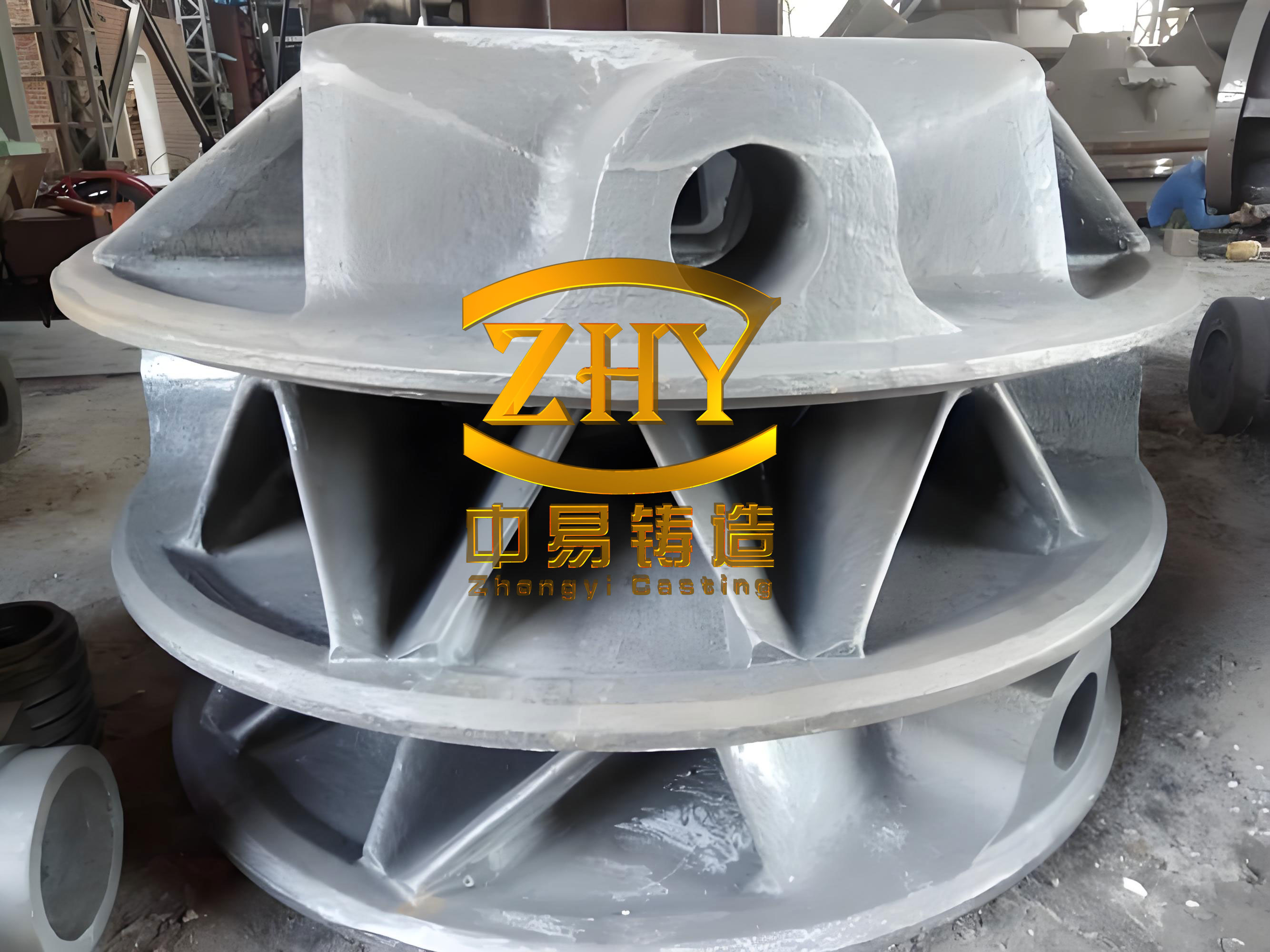
The planet carrier, with a net weight of approximately 3,260 kg, features a complex geometry including a central hub, multiple arms (long and short shafts), and connecting plates. Key sections, such as the roots of the shafts where they join the plates, represent critical thermal zones prone to shrinkage porosity and structural weaknesses. For this ductile iron casting, the material specification is EN-GJS-700-2U, requiring high tensile strength, yield strength, and a minimum elongation, alongside a pearlitic matrix structure. The casting process must address the inherent difficulties of thick-section ductile iron, such as ensuring graphite spheroidization, preventing shrinkage defects, and achieving the desired microstructure.
Our approach to this ductile iron casting project began with a comprehensive process analysis. We recognized that the success of producing a high-integrity ductile iron casting hinges on a synergistic combination of gating and feeding system design, precise melt chemistry control, effective inoculation and nodularization, and appropriate heat treatment. The gating system was designed to ensure laminar flow of molten metal into the mold cavity, minimizing turbulence and associated defects like slag inclusion and gas porosity. Given the size and geometry of this ductile iron casting, a bottom-gating system with multiple ingates was selected. This design allows the metal to fill the mold from the bottom upwards, promoting a stable filling sequence and reducing the risk of mold erosion and oxide formation.
The feeding system for this thick-section ductile iron casting combines the use of risers and chills. While theoretical modulus calculations might suggest the possibility of riser-less casting for sections with a modulus greater than 2.5 cm, the addition of alloying elements like manganese increases the shrinkage tendency of the iron. Therefore, to ensure soundness and maintain a safety margin, we employed a strategy of selective riser placement complemented by extensive use of chills. Riser s, positioned at the tops of the short shafts, serve a dual purpose: they provide liquid metal feed to compensate for solidification shrinkage and act as overflow wells to collect cooler, initial metal that may contain inclusions. Chills, made of cast iron or steel, are strategically placed in areas of high thermal concentration, such as the roots of the long shafts, bearing bores, and pin holes. Their primary function is to accelerate local solidification, refine the microstructure, prevent graphite degradation, and help direct solidification towards the risers or less critical areas. The use of chills is particularly crucial in ductile iron casting for wind components to enhance density and mechanical properties in key zones.
A critical aspect of producing a high-quality ductile iron casting is the meticulous control of chemical composition. The composition directly influences graphite morphology, matrix structure, and mechanical properties, especially in thick sections. For this pearlitic grade ductile iron casting, we adhered to a principle of high carbon and controlled silicon content. Carbon equivalent (CE) is a key parameter, and for this application, it was maintained between 4.2 and 4.3. The carbon equivalent for ductile iron is commonly calculated using the formula:
$$CE = C + \frac{Si + P}{3}$$
However, for more accurate control in alloyed irons, we focused on individual element ranges. Silicon content was kept relatively low (2.0% to 2.2%) to suppress graphite flotation and the formation of chunky graphite, which are common issues in thick-section ductile iron casting. Manganese, a carbide stabilizer, was restricted to below 0.5% to avoid promoting pearlite at the expense of excessive carbides and to ensure good toughness. Copper, added in the range of 0.5% to 0.6%, is a potent pearlite promoter that does not form carbides, thereby enhancing strength and hardness while maintaining a uniform microstructure across the section. Residual magnesium, essential for graphite spheroidization, was controlled between 0.04% and 0.06% to counteract magnesium fade during the long solidification period typical of this ductile iron casting. Rare earth elements, specifically yttrium-based heavy rare earths, were kept between 0.02% and 0.03% to improve nodule count and increase resistance to fading. The target base iron composition before treatment is summarized in Table 1.
| Element | Target Range | Role in Ductile Iron Casting |
|---|---|---|
| Carbon (C) | 3.5 – 3.8 | Promotes graphite formation, fluidity |
| Silicon (Si) | 1.2 – 1.4 (base); 2.0 – 2.2 (final) | Graphitizer, strengthens ferrite |
| Manganese (Mn) | ≤ 0.5 | Strengthens pearlite, but can form carbides |
| Phosphorus (P) | ≤ 0.05 | Impurity, forms brittle phosphides |
| Sulfur (S) | ≤ 0.015 | Impurity, consumes nodulizing elements |
| Copper (Cu) | 0.5 – 0.6 | Promotes and refines pearlite |
The nodularization and inoculation treatment processes are paramount for achieving a high nodule count and round graphite morphology in this ductile iron casting. We employed a sandwich method for nodularization using a yttrium-based heavy rare earth magnesium ferrosilicon alloy. The choice of yttrium-based alloy over light rare earth types was deliberate due to its stronger desulfurization capability, better nodule roundness, and superior fade resistance in thick sections. The addition rate was 1.15% to 1.25% of the molten metal weight. Inoculation was performed in multiple stages to ensure effectiveness throughout the solidification process. A primary inoculation with a barium-containing efficient inoculant (0.6% addition) was done during the treatment, followed by a stream inoculation during pouring (0.15% addition). This multi-stage inoculation helps in generating numerous graphite nucleation sites, countering chilling tendencies, and improving microstructure homogeneity in the final ductile iron casting.
Melting and pouring parameters were carefully optimized. The iron was superheated to 1500–1550 °C to ensure complete dissolution of charge materials and purification. The tapping temperature was controlled between 1460–1490 °C. To shorten the solidification time and reduce liquid shrinkage, the pouring temperature was deliberately lowered but kept within a range that prevents cold shuts and allows slag removal. The optimal pouring temperature for this ductile iron casting was established as 1340–1360 °C. The solidification time (t) for a casting can be approximated by Chvorinov’s rule:
$$t = k \cdot V^n$$
where \(V\) is the volume, and \(k\) and \(n\) are constants dependent on the mold material and casting geometry. Lowering the pouring temperature effectively reduces the initial heat content, thereby decreasing the solidification time constant for a given section, which is beneficial for controlling graphite structure in thick-section ductile iron casting.
Given the slow cooling inherent in such a massive ductile iron casting, achieving the required high pearlite content (≥75%) in the as-cast condition is extremely difficult. Therefore, a dedicated heat treatment cycle is indispensable. The heat treatment consists of a normalizing operation followed by a stress-relief tempering. The normalizing process involves austenitizing the casting at 900–920 °C for 5–8 hours to achieve a homogeneous austenitic structure, followed by forced cooling. The cooling rate after austenitizing is critical; insufficient cooling leads to the formation of excessive ferrite, degrading strength and hardness. For this ductile iron casting, forced air cooling was employed, with special attention to internal sections like the long shaft bores where heat extraction is slower. In some cases, mist cooling might be necessary for batch production to ensure uniform properties. The normalized casting is then tempered at 560–570 °C for 4–6 hours to relieve residual stresses and improve dimensional stability, followed by furnace cooling. The transformation kinetics during cooling can be related to continuous cooling transformation (CCT) diagrams for ductile iron, where the cooling rate must be sufficient to avoid the nose of the ferrite transformation region.
To virtually analyze and optimize the casting process before physical trials, we employed MAGMA numerical simulation software. The initial process design, featuring bottom gating, specific riser and chill placements, was modeled. The filling simulation confirmed a smooth, non-turbulent fill with metal front velocity below 2 m/s. The solidification simulation, however, revealed problematic areas. After approximately 46 minutes of simulated solidification, liquid metal isolation began at the long shaft root fillets. By the final stages of solidification (around 67 minutes), significant isolated liquid pools were predicted at the roots of the columns, particularly where they connect to the lower plate. The porosity prediction module of the software indicated a high risk of shrinkage defects in these areas, especially at the junction of the long shaft root and the lower plate, as shown in the simulation results. This necessitated process optimization.
Based on the simulation findings, the chilling strategy was revised. To address the column root shrinkage, conforming chills were added to enhance cooling at these fatigue-critical junctions. For the major hot spot at the long shaft root, a more comprehensive approach was taken. A continuous chill was placed around the outer cylindrical surface of the long shaft from its root to near the top. This ensures that the long shaft solidifies before the heavily sectioned junction area. Additionally, a ring of chills was arranged on the lower plate plane surrounding the shaft root. This helps to disperse the thermal center that would otherwise be pushed into the plate, potentially breaking down a concentrated shrinkage cavity into dispersed micro-porosity or eliminating it altogether. The principles of directional solidification were applied, aiming for a temperature gradient that promotes feed metal flow from the risers towards the last-to-solidify areas. The thermal gradient \(G\) and solidification rate \(R\) are key parameters; an optimal \(G/R\) ratio is sought to minimize shrinkage porosity in ductile iron casting.
The optimized process was re-simulated. The results showed a marked improvement. The long shaft solidified much earlier, becoming mostly solid after about 21 minutes, while maintaining an open feeding path to the lower plate junction. By 55 minutes, the isolated liquid zones in the columns had shifted to less critical mid-sections, and the problematic zone at the long shaft root had moved to less demanding interior regions of the lower plate. The porosity prediction indicated that the critical areas were now free of major shrinkage defects, with only minor, acceptable porosity redistributed to non-critical zones. Furthermore, the overall solidification time was reduced, which is beneficial for maintaining effective inoculation and nodularization in this thick-section ductile iron casting. The effectiveness of the optimization can be quantified by comparing the Niyama criterion values in critical regions before and after modification. The Niyama criterion \(N_y\) is given by:
$$N_y = \frac{G}{\sqrt{\dot{T}}}$$
where \(G\) is the temperature gradient and \(\dot{T}\) is the cooling rate at the end of solidification. Higher \(N_y\) values generally correlate with a lower risk of shrinkage porosity.
Following the optimized design, trial productions of the ductile iron casting were conducted. The castings were made using furan resin sand molds in a three-part flask arrangement to facilitate molding and core placement. After casting, machining, and heat treatment, the components underwent rigorous inspection. Ultrasonic testing (UT) and magnetic particle testing (MT) were performed according to relevant standards (e.g., EN 12680-3 and EN 1369). The results met the stringent requirements, with key areas achieving the highest quality grades. To verify the mechanical properties in the most demanding sections of the actual ductile iron casting,本体 samples were extracted from a prototype. Sampling locations included areas near the long shaft root and column roots—regions with large thermal modules and challenging cooling conditions during heat treatment. Four tensile specimens (labeled A through D from outer to inner regions) were machined from one such location. The mechanical properties and microstructural characteristics of both the attached test blocks (standard Y-blocks) and the casting本体 are presented in Table 2.
| Property / Requirement | Specification (EN-GJS-700-2U) | Attached Test Block Result | Casting Body Sample A | Casting Body Sample B | Casting Body Sample C | Casting Body Sample D |
|---|---|---|---|---|---|---|
| Tensile Strength, Rm (MPa) | ≥ 650 | 917 | 758 | 679 | 660 | 774 |
| Yield Strength, Rp0.2 (MPa) | ≥ 370 | 521 | 434 | 399 | 394 | 415 |
| Elongation, A (%) | ≥ 1 | 5.0 | 3.0 | 4.5 | 6.5 | 3.5 |
| Hardness (HB) | 210 – 305 | 290 | 275 | 259 | 252 | 269 |
| Nodularity Grade | ≥ 2 | 2 | 2 | 2 | 2 | 2 |
| Graphite Size Grade | ≥ 5 | 6 | 6 | 6 | 6 | 6 |
| Pearlite Content (%) | ≥ 75 | ~98 | ~85 | ~80 | ~80 | ~85 |
The data confirms that all properties exceeded the minimum requirements. The attached test block, benefiting from more favorable cooling during heat treatment, showed higher strength and pearlite content. The casting body samples, representing actual component sections, also comfortably met the specifications, demonstrating the effectiveness of the integrated process for this ductile iron casting. The microstructure in all cases showed well-formed spheroidal graphite (grade 2 nodularity) and a predominantly pearlitic matrix. The successful trial led to process qualification and subsequent batch production. Over a thousand units of this ductile iron casting have been manufactured with a yield rate exceeding 98%, validating the robustness of the developed methodology.
In conclusion, the production of high-integrity wind power planet carriers via ductile iron casting requires a holistic and optimized approach. Key findings from this research are: First, chemical composition must be precisely tailored, with a carbon equivalent of 4.2–4.3, controlled silicon (2.0–2.2%), low manganese (<0.5%), and alloying with copper (0.5–0.6%). Residual magnesium should be 0.04–0.06%, and rare earths (yttrium-based) 0.02–0.03% to ensure fade-resistant nodularization in thick sections. Second, the gating and feeding system should employ bottom gating with multiple ingates for calm filling, and a combination of risers and extensive, strategically placed chills to promote directional solidification and eliminate shrinkage in critical zones of the ductile iron casting. Third, melt treatment involving a yttrium-based heavy rare earth nodulizer and multiple-stage inoculation with efficient inoculants is essential for achieving a high nodule count and round graphite. Pouring temperature should be moderated to around 1340–1360 °C to reduce solidification time. Fourth, numerical simulation is an indispensable tool for visualizing filling and solidification, identifying defect-prone areas, and iteratively optimizing the chill and riser layout before costly physical trials. Fifth, heat treatment is mandatory to achieve the required pearlitic microstructure. Normalizing must involve a sufficiently rapid cooling rate, often requiring forced air or mist cooling, especially in internal sections, followed by tempering for stress relief. The entire process chain—from mold design and melt control to solidification management and heat treatment—must be meticulously controlled to consistently produce a reliable, high-performance ductile iron casting for demanding wind energy applications. This comprehensive methodology ensures that the ductile iron casting meets all mechanical, microstructural, and non-destructive examination standards, contributing to the durability and efficiency of wind power generation systems.