
1 Pump body materials, structural characteristics and requirements
The annual corrosion rate of zirconium is less than 0.05 mm, and it has excellent resistance to
corrosive, and zirconium materials are less likely to absorb hydrogen than other applicable materials.
Sensitive and therefore more suitable for chemical reaction conditions of high temperature and high pressure Pieces. Research on refractory materials suitable for zirconium metal is relatively rare at home and abroad. In actual production, the selection of refractory materials usually refers to titanium castings. The main refractory materials include: calcium oxide, thorium oxide, titanium carbide and graphite, etc. Chen Zhankao and others made a comprehensive analysis of suitable refractory materials for zirconium castings. Point out the feasibility of using graphite as refractory material for zirconium castings. Therefore, for the preparation of this large-scale high-temperature and high-pressure centrifugal zirconium pump casting, high-purity dense graphite is selected as the refractory material with simple synthesis process, relatively low preparation cost, and good machining performance.Moreover, the strength of graphite increases significantly with the increase of temperature, which is also a major advantage that other refractory materials cannot match.
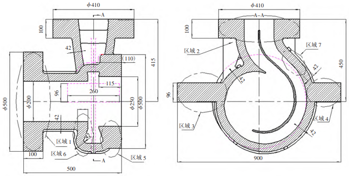
The structure of the zirconium pump body studied in this article is shown in Figure 1. Its structure
With large size and large wall thickness, the casting as a whole presents a “thick” state with many hot node locations. The pump body is a typical centrifugal pump volute structure. The overall structural size is 500 mm×900 mm×800 mm. The minimum wall thickness of the casting can reach 42 mm. The inlet flange size isφ500 mm×100 mm, outlet flange size is φ410 mm×100 mm, cantilevered support feet extending to the outer wall of the volute. In addition, there are 7 areas in the pump body that are prone to shrinkage holes, namely: area 1 at the inlet flange, area 2 at the outlet flange, and area 3 at the cantilever support foot.And area 4, area 5 at the pump body volute and area 6, area 7 at the outlet of the flow channel volute, especially area 7 is the location where the problem of shrinkage holes in the centrifugal pump body casting frequently occurs.
The castings comply with ASTM-B752 “Standard for Zirconium and Zirconium Alloy Castings”.
The casting accuracy of the castings is CT8 level, the radiographic inspection meets the requirements of ASTM standards E446 and E186, and must meet the secondary standards for defects of type A, B and C. The castings must be hot isostatically pressed. In addition, the delivery cycle of this casting is short, the material cost is high, and there is not much casting experience and related literature on large-scale zirconium castings. Therefore, based on the metal characteristics of zirconium alloys, the structural characteristics of the castings, and the actual production conditions, the number of trial productions should be reduced as much as possible to shorten the production time. Trial production cycle, improve the preparation success rate, reduce trial production costs, and choose a molding method that can not only meet the actual production conditions but also meet the design performance requirements, is crucial to actual production.
Figure 1 Schematic diagram of the structure of a large high temperature and high pressure zirconium pump body
If graphite mold is used as the refractory material in the preparation process of zirconium castings, will the large amount of gas generated by the graphite mold at the second gas generation peak become a problem?The successful discharge of the mold is crucial to the internal quality of the casting. Therefore, based on this research, this article selects machined split-type movable block graphite molds, adopts a pouring process with bottom injection as the main part and top injection as the supplement, and compares the flow effects of bottom injection mold filling with different cross-sectional ratios to ensure the accuracy of liquid filling. Stability and exhaust smoothness, grasp the key control points that affect the quality of large-scale zirconium castings, and realize large-scale high-temperature and high-pressure centrifugal zirconium pump body castings that meet technical requirements.
2 Analysis of the casting process of the pump body
2.1 Selection of parting surface
There are various parting methods for machined graphite type. In accordance with graphite casting
In addition to the basic parting principles [9], the inlet flange parting line, the flow channel center line parting line and the outlet flange parting line are adopted. Graphite mold production is divided into: lower mold, upper mold, No. 1 core, No. 2 core, No. 3 core, No. 4 core, import flange mold and export flange mold, and all flange molds All are designed with demolded sheets, and a hollow sand cleaning groove is designed on the back of the demolded sheets. The casting assembly is positioned and installed with stop buckles and graphite pins, and then tightened with tie rods. The casting parting line is selected as shown in Figure 2.
The design of the riser is: the feeder bevel angle of the riser is 10°, and the inlet
The top of the flange is equipped with a top riser, the outlet flange is equipped with a welt top riser, and the two supporting feet of the pump body are provided with a welt top riser. The exhaust design is as follows: a large number of φ6 exhaust holes are opened at the top of all risers, anti-overflow exhaust ducts are designed at the top of the outlet flange mold, and anti-overflow exhaust ducts are designed at the top of the riser at both support feet of the pump body. There are φ4 exhaust holes between the mold assembly surfaces, and there are φ5 exhaust holes on the sides of the inlet and outlet flange mold. There is no obstruction shrinkage size between the two flanges. According to the product Figure actual size design casting. The wall thickness of the casting is directly related to the pressure-bearing safety performance of the casting. Taking into account the shrinkage of the casting body, pickling, grinding and other post-processing casting thinning issues, the thickened runner mold is 3 mm. Double runner
The pump body needs to have a sand cleaning hole in the pump body. The design of the sand cleaning hole is as follows: 80 mm in length, 40 mm in width, and 45 mm in thickness at the upper right and lower right 35° directions of the pump body flow channel partition. There are two holes, and a φ5 exhaust slot connected to the casting mold is prepared on the surface of the sand-clearing hole graphite plugging plate. After the sand-clearing hole is cast, it is welded and vacuum annealed. The welds need to undergo penetration testing, weld ultrasonic flaw detection and radiographic testing.
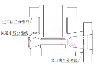
Figure 2 Parting line diagram of zirconium pump castings
2.2 Gating system design
The design principles of the gating system for zirconium castings have not been reported in the literature. In production practice, titanium casting technology is mainly used for design. Chen Zhankao and others studied the casting process of 20-inch zirconium right ball valves and pointed out that graphite type is used to prepare zirconium castings. The successful escape of graphite type physical and chemical adsorption gases is crucial to the internal quality of zirconium castings. They also pointed out that the bottom note Effect of process on graphite type exhaust Significantly. However, there are also problems with the bottom pouring system, such as: the slow flow rate causes the liquid barrel to overflow and burn out the pre-tightened iron wire, causing the container to expand, causing fire, contaminating the furnace, melting through the furnace body, etc.; the liquid barrel overflows and wraps the pre-tightened iron wire. clamp tightly The plate will increase the cleaning work in the later stage; the flow line of the molten metal is long and the mold filling time is long, which results in the low superheat of the molten metal and increases the difficulty of mold filling. These problems will lead to a lower pass rate of castings.
This article uses a pouring system with an open bottom cross runner to mainly solve the problem of stable filling and exhaust capabilities of molten metal. The design A pouring system that can take into account both exhaust and bottom injection and smooth filling is developed. The structure of the pouring system is shown in Figure 3. This pouring system can ensure the smooth injection of the metal liquid at the bottom, avoid splashing and turbulence of the metal liquid, and effectively reduce The apparent cold separation and number of flow marks of the casting after solidification ensure that the casting has relatively good apparent quality. In addition, the mold design at the inlet flange in Figure 3 ensures that the cavity is open to achieve maximum It has a optimized mold exhaust effect and can fill the mold when the bottom pouring system is shut down prematurely, ensuring the successful filling of the casting.
The pouring system shown in Figure 3 will lead to out-of-sequence filling if the proportion of the flow blocking section is designed unreasonably. According to the structural characteristics of the casting and the blank Weight, the vacuum consumable electrode shell furnace uses an 800 kg shell furnace. The furnace height limit is 1200 mm, and the crucible turning speed is 13 s±1s. The flow resistance area ratio of the titanium casting pouring system is set to S resistance:S within =1:2~4[9]. Since the maximum size of the funnel mouth of the 800 kg vacuum pouring furnace is φ100 mm, S resistance = 7 850 mm2, and the pouring volume is 650 kg, this paper designed two cross-sectional proportions of the bottom-cast open type Gating system, cross-sectional data are shown in Table 1.
Table 1 Inner runner blocking section data
| S resistance data | Blocking position: funnel mouth; The maximum size is 100 mm; S a 7 850 mm |
| Preset sprue | 4 circular inner runners evenly distributed |
| Pre set S resistance: within S | 1:2 1:2.5 |
| Inner sprue S/mm | 3925 4906 |
| Preset inner runner radius/mm | R=31 R=39 |
| Inner sprue radius after rounding/mm | R=35 R=40 |
| Actual S group: within S | 1:96 1:2.56 |
3 Analysis of bearing capacity of vacuum consumable electrode condensation furnace
3.1 Hydraulic system bearing capacity analysis Usually when pouring oversized castings in a vacuum consumable condensing furnace, the metal needs to be melted to the upper limit of the water-cooled copper crucible for pouring. Therefore, the crucible flipping of the vacuum consumable condensing furnace is particularly important, which directly Determines the success or failure of the casting. The large-scale high-temperature and high-pressure The zirconium pump body blank weighs 410 kg, the weight including the gating system is about 600 kg, the weight of the solidified shell is about 250 kg, and the total melting volume is about 850 kg. Through calculation, it can be seen that the maximum holding capacity of the crucible zirconium material is about 900 kg.The calculated maximum turning capacity of the furnace is 10 t. Theoretically, the crucible of the vacuum self-consumable condensing furnace can turn over smoothly. However, whether the hydraulic system of the equipment can withstand the large pressure under long-term and high-temperature conditions, the hydraulic system will not Whether the pressure drops rapidly due to seal leakage or other reasons, it is still unknown to ensure smooth pot turning under the condition of a total melting volume of 850 kg.
On-site counterweighting of the vacuum consumable condensing furnace 1 500 kg After manually turning the pot, it was found that the crucible of the vacuum self-consumable condensing shell furnace could operate normally, but the hydraulic system produced obvious oil leakage and pressure relief, and there was a pause of 3 to 5 seconds when turning the pot. Therefore, the turning hydraulic system of the vacuum consumable condensing furnace was completely disassembled and inspected, and it was found that the internal sealing ring was aged and the key valves were insensitive. Subsequently, the crucible turning hydraulic system was comprehensively overhauled and updated, and the system was re-installed.
The new setting of the turning speed is 10 s, and the total crucible turning time is 13 s±1 s under the condition of 1000 kg counterweight.
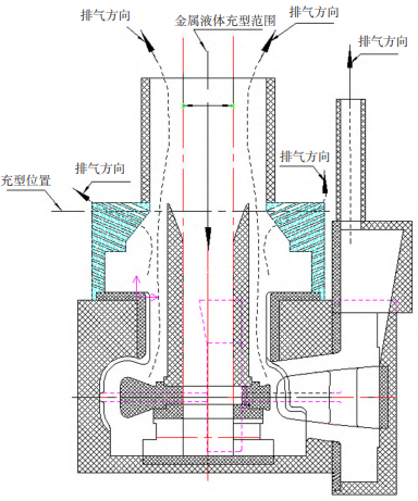
Figure 3 Schematic diagram of the casting structure of a large zirconium pump body
3.2 Analysis of circuit system carrying capacity
Usually, vacuum consumable shell condensing furnaces also require long-term melting when pouring oversized castings. Therefore, the circuit system endurance of vacuum consumable shell condensing furnaces is particularly important, which directly determines the success or failure of castings. The theoretical smelting time of the large-scale zirconium pump body studied in this article is about 30 minutes. The usual current parameters when smelting zirconium metal are: current 30 kA ~ 40 kA, voltage 40 V, vacuum degree less than about 2 Pa, crucible water pressure 0.2MPa, The outlet water temperature of the crucible is lower than 60°C. It is not 100% certain whether the circuit can be smelted at high temperature for a long time without overload protection.
In the same smelting time of the vacuum consumable shell furnace ,In the titanium material smelting test, it was found that the circuit of the shell condensation furnace was overload protected after about 15 minutes of smelting. After investigation, it was found that the coolant temperature in the rectifier cabinet of the equipment exceeded the safe melting upper limit during long-term smelting, and the equipment operating system performed a power-off safety self-protection operation. By shutting down the furnace and dismantling the coolant pipeline system of the electrical cabinet, it was found that
The external circulation cooling exchanger pipeline of the electrical cabinet is clogged and the flow rate is small, the internal circulation cooling water pipeline is connected incorrectly, the cooling water circulation path in the pipeline is shortened, and there is a dead water area in the conduit pipeline, causing the temperature of the electrical cabinet to exceed the upper limit of the overload protection temperature. By changing the water quality of the external circulation coolant of the electrical cabinet to deionized distilled water, changing the connection method of the coolant pipeline of the electrical cabinet, performing powerful air cooling outside the electrical cabinet and cooperating with power outages of other electrical equipment (reducing ,Light total circuit load), after actual furnace verification, it can be seen that the vacuum self-consumable shell furnace can carry out long-term melting for more than 35 minutes. Its verified current is 35 000 A, the voltage is 40 V, and the vacuum degree is less than about 2 Pa. The crucible water pressure is 0.2MPa, the crucible outlet water temperature can be controlled below 50 ℃, and the cooling water temperature of the electrical cabinet is below 45 ℃.
4 Graphite type manufacturing and casting
Graphite type requires high-density electrode graphite, dense graphite
Good strength and graphitization. Graphite with serious cracks and holes is not allowed to be used. The volume density is ≥1.58 g/cm3.In order to remove moisture and other volatile matter in graphite, the graphite type is first pre-baked. Put the graphite type into the holding furnace and preheat at 250°C for more than 8 hours. The graphite type is then roasted.The furnace should not be placed too closely, leaving a certain gap between each other to ensure that the gas in the graphite type can be discharged smoothly. After the graphite type has completed the vacuum degassing operation, assemble the furnace according to Figure 3, and use two longitudinal pressure rods at the same time. Four horizontal tie rods are cross-molded and bolted before spot welding to ensure that the mold does not expand. At the same time, it is necessary to adopt The graphite mold is wrapped with zirconium insulation cotton. In order to improve the fluidity and filling ability of the metal liquid, the assembled mold must be preheated at 350 ℃ ~ 400 ℃ for more than 4 hours before pouring. In order to control the melting stability and internal defective shrinkage holes from the source, the ingot is required to be cast three times. All surfaces of the ingot must be turned and exposed to light to remove the oxide layer, and the electrode must be cleaned and wiped before welding. When pouringA 1,000 kg Zr702C ingot that has been smelted three times was used for casting, and an 800 kg vacuum consumable electrode shell furnace was used for casting. The main smelting parameters are shown in Table 2. After the pouring is completed, the furnace cooling time is more than 4 hours,Or after the casting is cooled to below 200°C and released, after cleaning the core and mold, the casting undergoes riser cutting, grinding, X-ray inspection, HIP treatment, shrinkage hole repair welding, vacuum annealing, pickling and sandblasting.Waiting process.
5 Effect analysis
The S resistance of the large zirconium casting cast for the first time in this article: S is
1:1.96, after removing the gating system and riser from the inlet flange, it was found that the surface quality of the casting in the upstream part of the mold was poor, especially the surface quality of the inlet flange of the casting was extremely poor, with a large number of flow marks and cold gaps. And a long shrinkage hole appeared on the end face of the inlet flange. This shrinkage hole occupies nearly 60% of the length of the inlet flange, and the depth of the defect is About 15 mm away from the end face of the inlet flange, the specific defect condition is shown in Figure 4. In addition, when taking radiographs of the pump body, it was found that there was only one defect in the inlet flange, which was the long air shrinkage hole; there was an excessive air shrinkage hole defect at the neck of the outlet flange, and the other parts of the radiographic The filming results met the technical requirements. The reason for this situation may be that S resistance: S inner = 1:1.96 is selected, and the 4×φ70 mm bottom injection channel is selected for the inner runner. The liquid circulation capacity of the bottom injection channel is weak. When filling the mold, the metal liquid is filled to the end face of the inlet flange. This is When the bottom injection sprue is filled in advance, the top injection pouring system is opened prematurely, and the metal liquid is injected into the mold from the top. The filling metal liquid is filled out of order, and the high-temperature gas generated instantaneously in the mold cannot be discharged from the mold as shown in Figure 3. The inlet flange part should be discharged in time, and even the air-inflated type may occur.
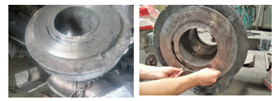
Figure 4 Defects in large zirconium pump body castings
In order to eliminate the air shrinkage hole defect on the end face of the import flange, the filling process must be The process satisfies the sequential filling of the bottom injection as the main injection and the top injection as the supplement. Adjust the S resistance: S to 1:2.5. The sprue size is still φ100 mm, and the inner runner is adjusted to 4×φ80 mm. After pouring, the overall casting The surface quality is better, especially the number of flow marks and cold insulation has been greatly improved compared with the trial product. by shooting into castings It was found by radiography that castings can be accepted by radiography in one go. By increasing S, it can be ensured that the auxiliary pouring system of the top injection does not open prematurely, and the large amount of gas released by the instant overheating of the graphite mold can be smoothly discharged from the mold, and the filling metal is relatively stable overall, and the surface of the casting is cold after solidification. and the number of flow marks will be reduced.
When graphite type is used as a refractory profile for pouring zirconium castings, it During injection, the temperature of the graphite mold will instantly exceed 250 ℃. In addition, the pouring temperature of the zirconium liquid is about 2 100 ℃. A large amount of molten metal will complete the complete filling of the mold within 13 s. Moreover, the graphite mold will also emit gas at the peak of 1 500 ℃. If the graphite mold stays for a long time, a large amount of gas will be generated at high temperature. If the mold is not vented smoothly, the gas pressure on the metal/graphite mold liquid surface will further increase, which can easily cause the gas to invade the metal zirconium liquid. In addition, The flow of molten metal is unstable, and a large amount of gas is generated when it is involved.
Eventually, a large number of pores are formed inside the casting. In order to achieve rapid mold filling and successful starting of the casting, the casting system is set to top pouring as the supplement and bottom pouring as the main method. The flow resistance section ratio is the open S resistance:
S = 2.5:1, allowing the casting to be filled smoothly and quickly from bottom to top to ensure that the gas generated during the pouring process can be smoothly discharged from the mold cavity, reducing the shrinkage cavity defects of the casting, and the casting can meet ASTM standards E446 and E186 stipulate that the internal quality of castings meets the requirements for passing the secondary standards for defects of Class A, B and C.
When casting zirconium castings in graphite type in vacuum solidification furnace, compared with titanium casting The gas volume of the piece is larger. When pouring zirconium castings, it is necessary to consider the gas release generated by the graphite mold in the primary and secondary gas generation peak areas. Under the premise that the pouring temperature can meet the fluidity and mold filling requirements, the superheat of the metal liquid can be reduced, and the temperature of the high-temperature liquid can be shortened. The residence time in the peak area of secondary gas generation will directly reduce the gas generation volume of the graphite type, fundamentally Minimize the source of gas as much as possible; graphite molds have the objective phenomenon of outgassing when heated, which cannot be avoided in actual production. However, by strengthening the exhaust process of the casting mold, the probability of gas generated by the graphite mold remaining inside the casting can be indirectly reduced.
6 Conclusion
1) When using graphite type to prepare zirconium castings, reduce the amount of gas at the first and second gas peaks of the graphite type to ensure that the gas generated by the graphite type
Successful escape has a significant effect on reducing the number and size of shrinkage holes inside the casting.
2) When pouring zirconium castings using a pouring system that can take into account exhaust gas and smooth filling of liquid bottom injection, it is necessary to ensure that the key flow blocking section proportions are required.
It is reasonable to prevent the turbulence of molten metal caused by opening the auxiliary gate too early.
3) High-purity graphite casting molds can be used to successfully prepare large-scale high-temperature and high-pressure centrifugal zirconium pump body castings with heavy weight, thick wall thickness, and good internal quality.