
In the field of advanced manufacturing, lost foam casting has emerged as a pivotal technique for producing intricate components with high dimensional accuracy and minimal post-processing requirements. This study delves into the application of lost foam casting for a challenging thin-walled cylinder block, specifically focusing on overcoming defects such as incomplete filling, sand inclusion, and leakage. The component under investigation is a wet-type four-cylinder block with a wall thickness of 6 mm, overall dimensions of 470 mm × 270 mm × 335 mm, and a weight of approximately 100 kg. Made from HT250 gray iron, the casting must withstand a hydraulic pressure test of 0.6 MPa without leakage, necessitating a robust process design. Through detailed analysis and optimization, we developed a comprehensive lost foam casting methodology that ensures high-quality output, as detailed in the following sections.
The structural complexity of the cylinder block posed significant challenges for lost foam casting. With numerous internal channels, small-diameter holes, and deep recesses, the pattern assembly and sand filling processes required meticulous planning. The wall thickness of 6 mm increases the risk of misruns due to rapid heat dissipation during pouring. To address this, we employed computational fluid dynamics (CFD) simulations to model the filling behavior, which highlighted the need for an optimized gating system and controlled pouring parameters. The governing equation for fluid flow in lost foam casting can be expressed as:
$$ \frac{\partial \rho}{\partial t} + \nabla \cdot (\rho \mathbf{v}) = 0 $$
where $\rho$ is the density of the molten metal, $t$ is time, and $\mathbf{v}$ is the velocity vector. This continuity equation, combined with momentum conservation, helps predict metal flow and prevent defects. Our simulations indicated that an inclined top-gating system would facilitate rapid filling while minimizing turbulence.
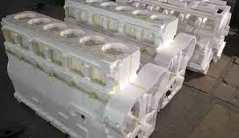
Pattern assembly is a critical step in lost foam casting, as it directly impacts the final casting quality. The cylinder block pattern was divided into four segments: two main body sections, one water channel section, and one oil channel section. These were fabricated from expanded polystyrene (EPS) with a density of 23–24 g/L to ensure lightweight yet stable patterns. We utilized a semi-automatic hot glue bonding machine for assembly, which enhanced precision and efficiency. The bonding process involved controlling the glue line width and traversal speed to avoid temperature variations and glue accumulation, which could lead to surface imperfections. The strength of the bonded pattern can be modeled using the following empirical formula for adhesive joints:
$$ \tau = \frac{F}{A} \leq \tau_{\text{max}} $$
where $\tau$ is the shear stress, $F$ is the applied force, $A$ is the bonded area, and $\tau_{\text{max}}$ is the maximum allowable stress for the adhesive. By maintaining optimal parameters, we achieved seamless pattern joints that withstood handling and coating processes without failure.
| Parameter | Value | Unit |
|---|---|---|
| EPS Density | 23–24 | g/L |
| Glue Line Width | 2–3 | mm |
| Bonding Speed | 10–15 | cm/s |
| Pattern Segments | 4 | – |
The casting process was designed with an inclined top-gating system to ensure rapid and complete mold filling. The gating system featured a cross-sectional dimension of 40 mm × 50 mm, with an ingate of 65 mm × 8 mm. A foam filter (10 PPI) measuring 50 mm × 100 mm × 20 mm was placed at the base of the sprue to trap inclusions and improve metal cleanliness. The pouring temperature was set between 1,495°C and 1,510°C to counter the high cooling rate associated with thin walls. The filling time for lost foam casting can be estimated using the following relationship derived from Bernoulli’s principle:
$$ t_f = \frac{V}{A \cdot v} $$
where $t_f$ is the filling time, $V$ is the mold cavity volume, $A$ is the ingate cross-sectional area, and $v$ is the flow velocity. By optimizing these parameters, we achieved a filling time of less than 5 seconds, which prevented cold shuts and misruns. The pattern was positioned at an angle during molding to facilitate sand compaction in complex areas, eliminating the need for manual sand ramming in water and oil channels.
| Parameter | Value | Unit |
|---|---|---|
| Sprue Cross-Section | 40 × 50 | mm² |
| Ingate Cross-Section | 65 × 8 | mm² |
| Pouring Temperature | 1,495–1,510 | °C |
| Filter PPI | 10 | – |
| Filling Time (Estimated) | 4–5 | s |
Coating application is vital in lost foam casting to ensure surface quality and prevent metal penetration. We used a KY-II type coating with high permeability, applied via three dipping cycles. The Baumé density was controlled at 74–76 for the first dip and 60–62 for subsequent dips. The coated patterns were dried in a controlled oven, and critical areas such as internal channels were touch-coated to avoid burns. The coating thickness $\delta_c$ influences the gas permeability, which can be described by Darcy’s law for flow through porous media:
$$ Q = \frac{k A \Delta P}{\mu L} $$
where $Q$ is the gas flow rate, $k$ is the permeability coefficient, $A$ is the area, $\Delta P$ is the pressure difference, $\mu$ is the dynamic viscosity, and $L$ is the coating thickness. The KY-II coating exhibited a permeability of $k = 2.5 \times 10^{-12} \, \text{m}^2$, which facilitated efficient degassing during pouring. Post-drying, the patterns were inspected for uniformity, with a target dry coating thickness of 0.8–1.2 mm.
| Parameter | First Dip | Second & Third Dip | Unit |
|---|---|---|---|
| Baumé Density | 74–76 | 60–62 | – |
| Dipping Speed | Slow (5–10 rpm) | Slow (5–10 rpm) | rpm |
| Drying Temperature | 50–60 | 50–60 | °C |
| Drying Time | 4–6 | 4–6 | h |
| Coating Thickness (Dry) | 0.8–1.2 | 0.8–1.2 | mm |
Molding and pouring were conducted with two patterns per flask to maximize productivity. The patterns were placed in the flask at an inclined orientation, and sand was added manually followed by compaction on a three-dimensional vibration table. The vibration time was set to 80 seconds, split into two cycles, to achieve uniform sand density without pattern distortion. After vibration, the sprue top was sealed with clay, covered with plastic film, and topped with 30–40 mm of facing sand. For melting, we used a charge composition of 10% pig iron, 70% high-quality scrap steel, and 20% returns, with carbon additives to achieve the desired carbon equivalent. Inoculation was performed in the ladle using a silicon-strontium and silicon-barium compound, followed by stream inoculation with silicon-strontium. Copper and tin were added to enhance hardness and mechanical properties. The chemical composition of the molten iron, as verified through spectroscopy, is summarized in the table below.
| Element | Heat 1 | Heat 2 | Heat 3 | Unit |
|---|---|---|---|---|
| C | 3.18 | 3.24 | 3.25 | % |
| Si | 1.84 | 1.81 | 1.90 | % |
| Mn | 0.80 | 0.84 | 0.92 | % |
| S | 0.075 | 0.074 | 0.074 | % |
| P | 0.032 | 0.031 | 0.031 | % |
| Cr | 0.24 | 0.25 | 0.24 | % |
| Cu | 0.08 | – | – | % |
| Sn | 0.050 | 0.047 | 0.044 | % |
After pouring, the castings were cooled for approximately 3 hours before shakeout. The gating systems were removed, and the castings underwent shot blasting to clean the surfaces. Visual inspection revealed clear contours with no signs of metal penetration or misruns. The castings were then ground to smooth any minor irregularities and coated with a paint layer of 60–100 μm thickness. Dimensional checks confirmed compliance with design specifications, and the castings were dispatched for machining validation. During machining, no defects such as sand holes, slag inclusions, or black skin were observed, and all critical dimensions met the requirements. The hydraulic test at 0.6 MPa confirmed leak-tightness, validating the efficacy of the lost foam casting process.
The success of this project underscores the versatility of lost foam casting for producing complex thin-walled components. Key factors included the inclined top-gating system, which ensured rapid filling; the semi-automatic pattern bonding, which improved accuracy; and the high-permeability coating, which prevented defects. The process parameters, such as pouring temperature and vibration time, were optimized based on theoretical models and practical trials. For instance, the solidification time $t_s$ for thin sections can be approximated using Chvorinov’s rule:
$$ t_s = k \left( \frac{V}{A} \right)^2 $$
where $k$ is a constant dependent on the mold material and metal properties. For our setup, $k$ was calibrated to 1.2 $\text{min/cm}^2$, resulting in a solidification time of about 8 minutes for the 6 mm walls. This controlled solidification minimized residual stresses and cracking. Future work will focus on automating the pattern assembly further and exploring advanced coatings to enhance the lost foam casting process for even more demanding applications.
In conclusion, the lost foam casting technique demonstrated exceptional capability in manufacturing the 394A wet four-cylinder block. By integrating analytical models with practical optimizations, we achieved a defect-free production rate that meets industrial standards. The repeated emphasis on lost foam casting throughout this study highlights its critical role in modern foundry practices, particularly for components requiring high precision and complex geometries. This research contributes to the broader adoption of lost foam casting by providing a reproducible framework for similar challenges.