
In modern industrial applications, thin-walled circular components are extensively used in sectors such as construction, automotive manufacturing, and petrochemical engineering due to their demand for excellent comprehensive mechanical properties and high density. However, the casting of these parts often presents significant challenges, including issues like misruns, cold shuts, shrinkage porosity, and other defects, primarily due to their slender geometry and rapid solidification characteristics. The lost foam casting process has emerged as a promising solution for such components, as it simplifies production steps, enhances dimensional accuracy, and supports environmentally friendly manufacturing practices. This study focuses on optimizing the lost foam casting process for medium-sized thin-walled circular parts through numerical simulation and practical validation, aiming to address common defects and improve production efficiency.
The structural design of thin-walled circular parts typically involves large radii and minimal wall thicknesses, which exacerbate the risk of incomplete filling and thermal stresses during casting. For instance, a representative circular part with an outer diameter of 435 mm, an inner diameter of 311 mm, and a maximum thickness of only 19 mm, with edge thicknesses as low as 10 mm, exemplifies these challenges. In the lost foam casting process, the foam pattern is coated and embedded in unbonded sand, and molten metal is poured to replace the pattern, leading to vaporization. This method reduces turbulence and minimizes gas entrapment, but the high cooling rate imposed by the coating can impair fluidity, necessitating precise control over pouring parameters. To overcome these limitations, a stepped gating system was designed, incorporating multiple ingates and risers to ensure uniform filling and effective feeding. Additionally, clustering five parts into a single mold assembly was adopted to enhance yield and economic viability, leveraging the advantages of lost foam casting for high-volume production.
Numerical simulation plays a critical role in predicting and mitigating casting defects. Using ProCAST software, the filling and solidification processes were analyzed to evaluate temperature distributions, solidification patterns, and potential defect formation. The finite element model comprised the foam pattern, a 2 mm thick coating, and a virtual sandbox filled with zircon sand, as summarized in Table 1. The material properties and process parameters were defined to replicate real-world conditions, with the alloy QT500-7 having a liquidus temperature of 1209.0°C and a solidus temperature of 1127.4°C. Pouring temperature was maintained at 1430 ± 10°C, with a total pouring time of 30 seconds. The interfacial heat transfer coefficients between the metal-coating and coating-sand interfaces were set at 500 W/(m²·K) to account for the chilling effect, which is crucial for thin-walled sections.
| Parameter | Value | Description |
|---|---|---|
| Foam Material | STMMA | Pre-expansion density of 18-20 g/L |
| Coating Thickness | 2 mm | Water-based coating for steel castings |
| Sand Type | Zircon Sand | Grain size: 2 ± 1 mm |
| Pouring Temperature | 1430 ± 10°C | Controlled to ensure fluidity |
| Interfacial Heat Transfer | 500 W/(m²·K) | Between metal-coating and coating-sand |
| Solidification Range | 1209.0°C – 1127.4°C | For QT500-7 alloy |
The thermal behavior during lost foam casting can be described using the heat conduction equation, which governs the temperature evolution in the system. The general form is given by:
$$ \frac{\partial T}{\partial t} = \alpha \nabla^2 T $$
where \( T \) is the temperature, \( t \) is time, and \( \alpha \) is the thermal diffusivity, defined as \( \alpha = \frac{k}{\rho c_p} \), with \( k \) being the thermal conductivity, \( \rho \) the density, and \( c_p \) the specific heat capacity. For the coating and sand, the effective thermal properties influence the cooling rate, which is pivotal in avoiding defects like cold shuts. In lost foam casting, the vaporization of the foam pattern introduces additional complexity, but for simulation purposes, the process is modeled as a transient heat transfer problem with phase change. The solidification kinetics can be approximated using the Scheil equation for non-equilibrium conditions:
$$ f_s = 1 – \left( \frac{T_L – T}{T_L – T_S} \right)^{\frac{1}{1-k}} $$
where \( f_s \) is the solid fraction, \( T_L \) and \( T_S \) are the liquidus and solidus temperatures, respectively, and \( k \) is the partition coefficient. This helps in predicting the formation of shrinkage porosity, which is minimized by the expansion of graphite in ductile iron, as in QT500-7.
The simulation results for the temperature field during filling and solidification revealed a progressive and uniform process. At 2.05 seconds, molten metal entered the sprue and runners, and by 5.66 seconds, it began filling the cavity through the bottom ingates, exhibiting laminar flow without turbulence. This is critical in lost foam casting to prevent gas entrapment and carbon defects. The stepped gating system allowed for sequential filling, with the top ingates activating at 26.73 seconds, providing thermal compensation and maintaining metal fluidity. By 34.00 seconds, filling was complete, with no misruns observed. The temperature gradients were steepest at the inner and outer radii due to the chilling effect of the coating, leading to rapid solidification initiation. As solidification progressed, the outer layers solidified first, forming a rigid shell that constrained the liquid core, while the graphite expansion in ductile iron compensated for volumetric shrinkage, reducing the risk of porosity.
To quantify the solidification behavior, the solid fraction evolution was analyzed. The initial stages showed rapid solidification at the surfaces, with the core remaining liquid for longer durations. The solid fraction \( f_s \) as a function of time and position can be correlated with the cooling rate \( \dot{T} \), which is higher in thin sections. For a circular geometry, the solidification time \( t_s \) can be estimated using Chvorinov’s rule:
$$ t_s = B \left( \frac{V}{A} \right)^n $$
where \( V \) is the volume, \( A \) is the surface area, \( B \) is a mold constant, and \( n \) is an exponent typically around 2 for sand castings. In this case, the high surface-area-to-volume ratio of the thin-walled part resulted in short solidification times, promoting directional solidification from the walls inward. The stress distribution was also evaluated, with the von Mises stress peaking at 231.2 MPa near the ingate and riser connections, but remaining below the yield strength of 320 MPa for QT500-7 elsewhere, indicating minimal risk of deformation during handling or machining.
Defect analysis using the simulation software indicated no significant shrinkage porosity or cold shuts, attributable to the optimized gating and feeding system. The stepped gates ensured adequate metal flow and temperature maintenance, while the risers provided necessary feeding until the late stages of solidification. The distortion analysis showed maximum deformations of 0.63 mm in the gating system, but the circular part itself exhibited minimal distortion, with radial deviations under 0.62 mm and axial deformations below 0.16 mm, well within the machining allowance of 2 mm. This underscores the effectiveness of the lost foam casting process in maintaining dimensional stability for thin-walled components.
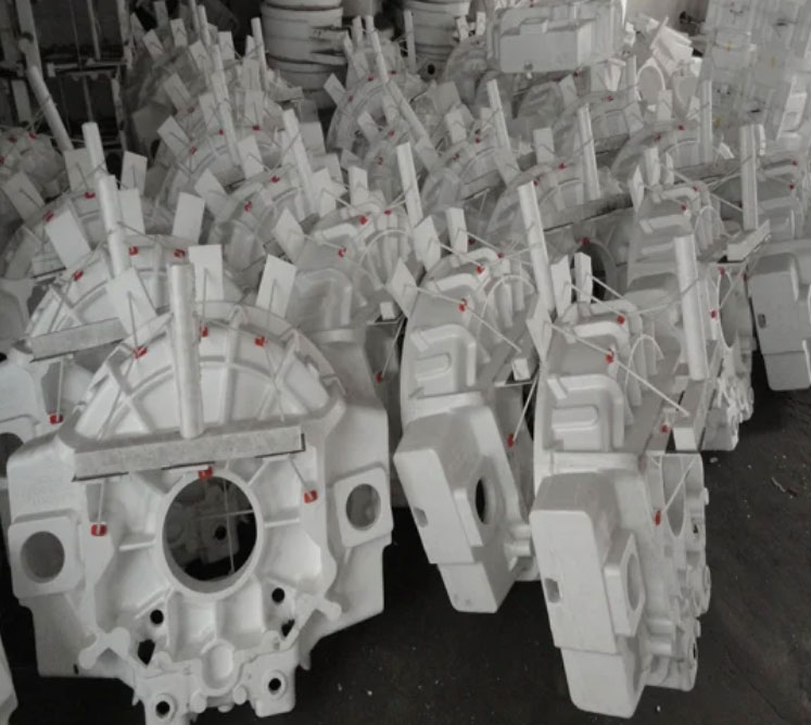
Practical trial production was conducted to validate the simulation findings. The foam patterns were made from STMMA copolymer, pre-expanded to a density of 18-20 g/L using a DH-450 intermittent pre-expansion machine under steam pressure of 0.14-0.18 MPa. After aging for over 24 hours, the patterns were molded, assembled, and coated with a water-based coating, dried at 50°C for 72 hours. The mold was assembled with zircon sand, and the cluster of five parts was poured under a vacuum of 0.06 MPa. Post-casting, the parts were cleaned, and the gating system was removed. The final machined components showed no defects such as shrinkage porosity, slag inclusion, or distortion, confirming the simulation predictions. The successful implementation highlights the robustness of the lost foam casting process for producing high-quality thin-walled circular parts efficiently.
In conclusion, the integration of numerical simulation with practical lost foam casting processes enables the optimization of gating designs and process parameters for medium thin-walled circular parts. The stepped gating system and clustering approach not only enhance filling efficiency but also mitigate common defects through controlled solidification. The absence of shrinkage porosity and cold shuts in both simulation and production trials demonstrates the viability of this method. Future work could explore the impact of varying coating materials or alloy compositions on the lost foam casting process, further expanding its applications in industrial manufacturing. This research provides a foundational framework for advancing lost foam casting techniques, ensuring high integrity and cost-effectiveness for complex thin-walled geometries.
The lost foam casting process, with its inherent advantages of reduced environmental impact and simplified production, proves highly suitable for such applications. By repeatedly applying lost foam casting principles, manufacturers can achieve consistent results, as evidenced by the minimal defects and high dimensional accuracy in this study. The use of advanced simulation tools like ProCAST allows for precise control, making lost foam casting a preferred choice for challenging components. As industries continue to demand lighter and stronger parts, the adoption of lost foam casting will likely grow, driven by its ability to meet stringent quality standards while maintaining efficiency.