
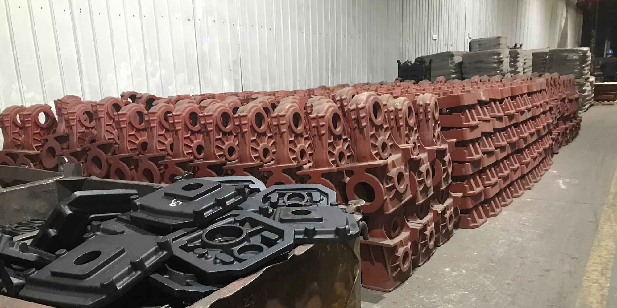
In the oil and gas industry, blowout preventers (BOPs) serve as critical well-control equipment, essential for managing wellhead pressure during drilling, workover, and testing operations. The BOP housing, a core component in deep-well drilling, is typically manufactured from high-strength low-alloy steel castings. These steel castings, such as those made from ASTM A487 Grade 4, exhibit excellent mechanical properties through precise composition adjustments and heat treatment. However, as primary pressure-bearing parts, defects in these steel castings necessitate repair welding. Incorrect welding procedures can lead to severe hardness reduction, coarse grain structure, and diminished mechanical performance, compromising the safety of well-control equipment. This study focuses on developing and validating welding processes for defect repair in BOP steel castings, ensuring compliance with industry standards like API 16A and NACE MR0175/ISO 15156.
Steel castings are pivotal in heavy-duty applications due to their versatility and strength. For BOP components, the material ASTM A487 Grade 4 is commonly used, characterized by its medium-high carbon and low-alloy composition. The chemical composition of this steel casting material is detailed in Table 1. The weldability of such steel castings is often assessed using carbon equivalent (CE) formulas recommended by the International Institute of Welding. A high CE value indicates greater hardenability and susceptibility to cold cracking. For ASTM A487 Grade 4, the CE is calculated as follows:
$$CE = C + \frac{Mn}{6} + \frac{Cr + Mo + V}{5} + \frac{Ni + Cu}{15}$$
Substituting typical values from Table 1, the CE approximates 0.77%, signifying poor weldability and a high risk of cold cracks. Thus, selecting appropriate filler metals, controlling welding parameters, and implementing post-weld heat treatment are crucial for successful repair of steel castings.
| Element | C | Si | Mn | P | S | Cr | Ni | Mo |
|---|---|---|---|---|---|---|---|---|
| Standard Range | 0.25-0.33 | 0.4-0.7 | 0.8-1.2 | ≤0.025 | ≤0.025 | 0.5-1 | 0.4-0.8 | 0.25-0.45 |
Two welding processes were investigated for repairing defects in BOP steel castings: Process 1 involves welding in the as-cast condition followed by full quality heat treatment (quenching and tempering), while Process 2 involves welding in the quenched and tempered condition followed by stress relief heat treatment. The selection of filler metals is critical to match the base metal’s properties. For Process 1, an E10015-G modified electrode was chosen based on composition matching, whereas for Process 2, an E9015-B3 modified electrode was selected for its comparable carbon equivalent and strength. The filler metal compositions are summarized in Table 2.
| AWS Classification | C | Si | Mn | P | S | Cr | Ni | Mo |
|---|---|---|---|---|---|---|---|---|
| E10015-G | 0.13 | 0.42 | 1.59 | 0.0102 | 0.0016 | 1.62 | 0.51 | 0.55 |
| E9015-B3 | 0.083 | 0.22 | 0.83 | 0.009 | 0.006 | 2.25 | 0.05 | 1.06 |
Welding procedure qualifications were conducted according to ASME Section IX. For Process 1, a test plate of dimensions 450 mm × 250 mm × 50 mm was prepared, and welding was performed using a non-penetration butt joint. A 4.0 mm diameter electrode was used for root passes, and 5.0 mm electrodes for filler passes. Preheating was maintained at a minimum of 180°C, with interpass temperatures between 200°C and 350°C. The welding parameters, including current, voltage, and speed, were controlled to manage heat input. Post-weld, a holding treatment at 350°C for 2 hours was applied to prevent cold cracking, followed by full heat treatment consisting of austenitizing, quenching, and tempering. The tempering cooling rate was carefully controlled to avoid residual stresses.
For Process 2, welding was carried out on quenched and tempered steel castings. To minimize heat-affected zone (HAZ) brittleness, low heat input was employed using small-diameter electrodes and multilayer multipass welding in the horizontal position. Preheating was set at 150°C, with interpass temperatures between 150°C and 200°C. The welding parameters are detailed in Table 3. After welding, stress relief heat treatment was conducted at 620-670°C for over 8 hours, with controlled heating and cooling rates to reduce residual stresses without affecting the base metal’s tempered microstructure.
| Parameter | Process 1 | Process 2 |
|---|---|---|
| Preheat Temperature | ≥180°C | 150°C |
| Interpass Temperature | 200-350°C | 150-200°C |
| Welding Current | 130-240 A | 150-200 A |
| Arc Voltage | 15-30 V | 18-25 V |
| Welding Speed | 10-20 cm/min | 20-30 cm/min |
| Post-weld Treatment | 350°C for 2 h, then full heat treatment | 350°C for 2 h, then stress relief at 620-670°C |
The welding heat input (E) is a critical factor influencing microstructural changes, calculated as:
$$E = \frac{V \times I \times 60}{S \times 1000}$$
where E is in kJ/mm, V is voltage in volts, I is current in amperes, and S is welding speed in mm/min. For Process 2, low heat input helps restrict grain growth in the HAZ, preserving toughness in these steel castings.
Non-destructive testing and mechanical property evaluations were performed per API 16A and NACE MR0175/ISO 15156. The requirements for BOP pressure-containing parts include tensile strength ≥655 MPa, yield strength ≥551 MPa, elongation ≥18%, reduction of area ≥35%, Charpy V-notch impact energy ≥42 J at -29°C, and a narrow hardness range of 207-237 HBW (or 207-248 HV10). Hardness testing was conducted across the weld metal, HAZ, and base metal, as illustrated in the standard method, with values converted using ASTM E140-12b. Impact test specimens were extracted from specific locations, including weld metal, fusion line, and areas 2 mm from the fusion line.
The results of mechanical tests are presented in Table 4. Both processes met the stringent requirements for steel castings. Process 1, with post-weld quality heat treatment, showed refined microstructure in the weld zone, resulting in uniform hardness and high impact toughness. Process 2, with stress relief heat treatment, also achieved satisfactory properties, though with a slightly wider hardness spread due to thermal effects on the HAZ.
| Process | Tensile Strength (MPa) | Yield Strength (MPa) | Elongation (%) | Reduction of Area (%) |
|---|---|---|---|---|
| Process 1 | 692.9 / 682.3 | 563.8 / 564.1 | 24.6 / 23.8 | 70 / 70 |
| Process 2 | 677.1 / 684.6 | 561.5 / 563.1 | 24.06 / 23.46 | 68.9 / 61.7 |
Hardness measurements across the weld regions are summarized in Table 5. For Process 1, hardness values ranged from 207 HV to 225 HV, demonstrating good uniformity. For Process 2, hardness varied from 207 HV to 249 HV, with higher values in the weld metal due to the filler metal’s composition and thermal cycles. The narrow hardness interval is crucial for stress corrosion cracking resistance in steel castings used in sour service environments.
| Process | Point 1 | Point 2 | Point 3 | Point 4 | Point 5 | Point 6 | Point 7 | Point 8 | Point 9 | Point 10 |
|---|---|---|---|---|---|---|---|---|---|---|
| Process 1 | 210 | 208 | 224 | 213 | 208 | 225 | 220 | 209 | 217 | 210 |
| Process 2 | 208 | 217 | 209 | 242 | 247 | 212 | 207 | 210 | 217 | 215 |
| (Additional points 11-19 show similar ranges, with Process 2 having higher variability.) | ||||||||||
Charpy impact test results at -29°C are listed in Table 6. Process 1 exhibited high impact energies in all zones, exceeding 60 J, indicating excellent toughness. Process 2 also met the 42 J requirement, with values ranging from 56 J to 133 J, though the HAZ showed lower toughness due to microstructural changes. The impact energy (KV) can be related to microstructure via empirical models, but the key takeaway is that both processes yield acceptable toughness for BOP steel castings.
| Process | Weld Metal Upper | Weld Metal Lower | Fusion Line Upper | Fusion Line Lower | Fusion Line +2 mm Upper | Fusion Line +2 mm Lower | Base Metal |
|---|---|---|---|---|---|---|---|
| Process 1 | 118 | 63.7 | 107.7 | 78.3 | – | – | 128.7 |
| Process 2 | 124.8 | 133 | 61 | 59 | 56 | 99 | 101 |
Metallographic analysis of Process 2 revealed a columnar grain structure in the weld metal, consisting of martensite, bainite, and ferrite mixtures. The HAZ displayed lath martensite with small amounts of tempered troostite, formed due to repeated heating during multilayer welding. The base metal showed uniform lath martensite. These microstructural observations explain the hardness and toughness variations. The hardness difference (ΔH) between zones can be expressed as:
$$\Delta H = H_{HAZ} – H_{WM}$$
where H_HAZ is HAZ hardness and H_WM is weld metal hardness. For optimal performance in steel castings, ΔH should be minimized to avoid stress concentrations.
In discussion, the carbon equivalent plays a pivotal role in weldability of steel castings. The high CE of ASTM A487 Grade 4 necessitates careful thermal management. Process 1, with full heat treatment post-welding, allows for microstructure homogenization, enhancing overall properties. Process 2, with localized heat input, requires precise control to prevent HAZ softening or embrittlement. The choice between processes depends on defect size and production constraints. For minor defects in steel castings, Process 2 is efficient, while for major repairs, Process 1 ensures superior properties. Both processes enable compliant repair of steel castings for critical applications.
Further considerations include the effect of welding on residual stresses. The stress relief heat treatment in Process 2 reduces stresses but must stay below the tempering temperature to avoid over-softening. Mathematical modeling of temperature distribution during welding can optimize parameters. The temperature field T(x,y,z,t) can be described using heat conduction equations:
$$\rho c \frac{\partial T}{\partial t} = \nabla \cdot (k \nabla T) + Q$$
where ρ is density, c is specific heat, k is thermal conductivity, and Q is heat source from welding. Such analyses aid in designing welding procedures for complex steel castings.
In conclusion, this study demonstrates two viable welding processes for defect repair in BOP steel castings. Process 1, involving welding in the as-cast state followed by quality heat treatment, produces a uniform microstructure with narrow hardness range and high impact toughness. Process 2, involving welding in the quenched and tempered state with subsequent stress relief, also meets standards when using low heat input and controlled interpass temperatures. Both processes satisfy API 16A and NACE MR0175/ISO 15156 requirements, ensuring the reliability of steel castings in well-control equipment. Future work could explore automated welding techniques or advanced filler metals to further enhance the repair of steel castings in the energy sector.