
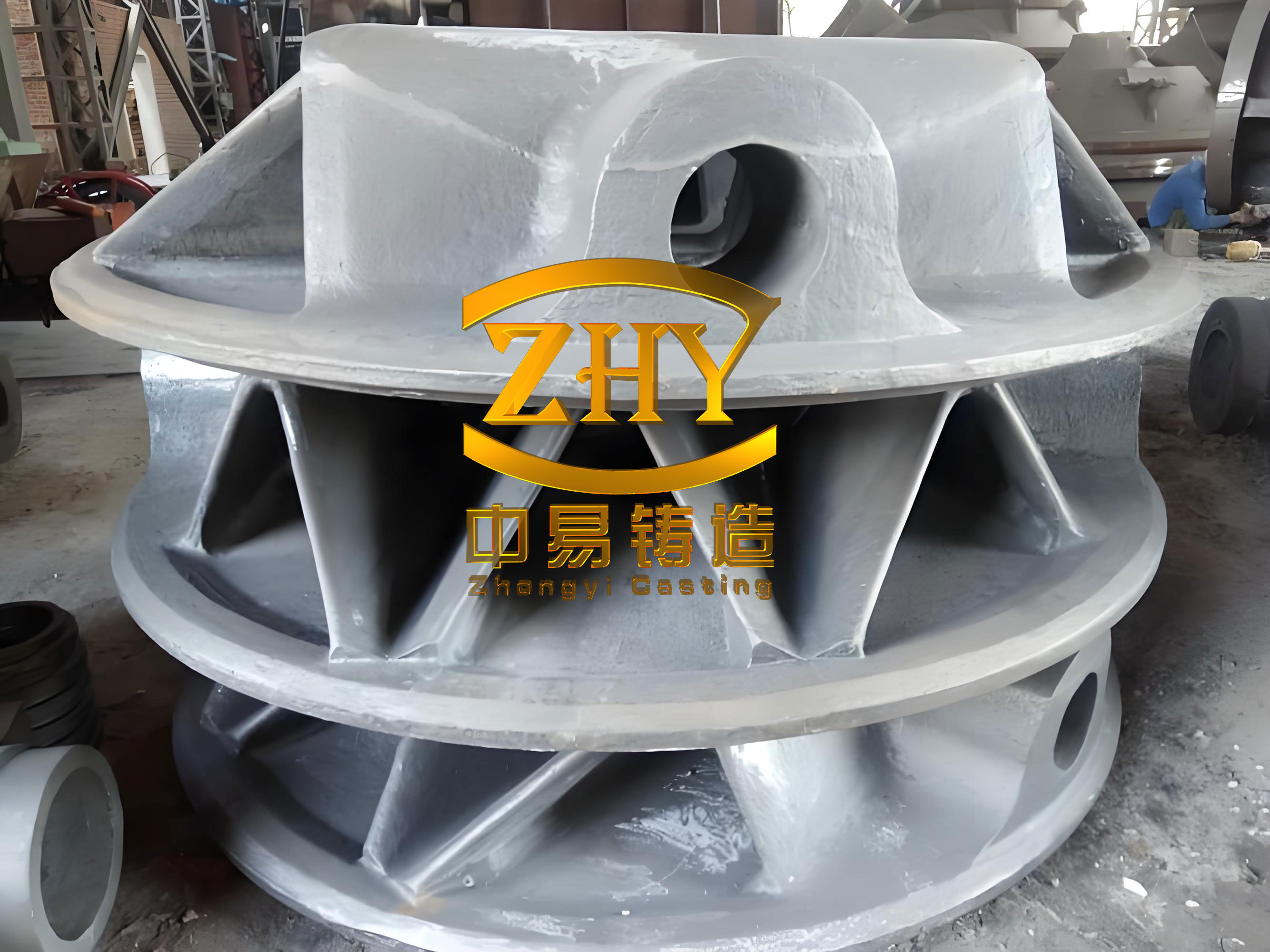
Large ductile iron castings are critical load-bearing components in wind turbines, heavy machinery, and nuclear equipment. Their service conditions demand high strength, low-temperature toughness, internal soundness, and consistent dimensional accuracy. In my experience with ductile iron casting, conventional resin-bonded sand molds often lead to coarse microstructures, shrinkage porosity, and poor batch consistency, especially in heavy sections. To address these problems, I developed and validated an alternative route based on sand-lined metal mold casting. This process combines the rapid cooling of a metal mold with the surface quality and thermal buffering of a thin resin-coated sand layer. In the following sections, I describe the process characteristics, design principles, and a full-scale production trial for a 22 t wind turbine main shaft made of QT400-18L ductile iron.
1. Why Large Ductile Iron Castings Require a Different Approach
In my work on heavy-section ductile iron casting, I have repeatedly observed that the solidification behavior of a 22 t component is fundamentally different from that of a 50 kg component. The thermal modulus, the heat capacity of the mold, and the time available for graphite expansion all scale with the casting mass. For a large ductile iron casting, the mold acts as a massive heat sink. If the mold is made of resin-bonded sand, its low thermal conductivity and low rigidity allow the mold wall to yield under the ferrostatic pressure and the graphite expansion pressure. This yielding increases the effective volume of the mold cavity and promotes shrinkage porosity. I therefore turned to a sand-lined metal mold, where a high-rigidity iron mold provides the structural constraint and a thin sand layer moderates the initial chill.
In my design philosophy, the sand-lined metal mold is not simply a metal mold with a wash. It is a composite tooling system in which the iron mold stores and removes heat, while the sand layer controls the local heat transfer coefficient. For small castings, the iron mold mainly acts as a chill. For large ductile iron castings, the iron mold becomes a true thermal reservoir that operates for tens of hours. This changes the design rules for sand thickness, mold wall thickness, gating, and feeding. I will explain these rules and then apply them to a wind turbine main shaft.
2. Process Characteristics of Sand-Lined Metal Mold Casting for Large Ductile Iron Castings
I summarize the key characteristics in Table 1. The table contrasts small castings with large ductile iron castings because the same process parameters have different meanings at different scales.
| Characteristic | Small ductile iron casting | Large ductile iron casting |
|---|---|---|
| Thermal role of iron mold | Local chill; short solidification time | Massive heat sink; sustained cooling for tens of hours |
| Sand layer function | Local adjustment of chill | Global zoning; different thickness for heavy and thin sections |
| Self-feeding by graphite expansion | Minor effect | Dominant effect; determines internal soundness |
| Dimensional accuracy | Good | Excellent; machining allowance can be reduced |
| Tooling cost | Easily amortized in mass production | High; suitable for stable batches of high-value castings |
| Thermal fatigue of iron mold | Low | High; requires strict material and life management |
In my analysis, the most important advantage for large ductile iron casting is the combination of rapid cooling and high rigidity. The rapid cooling refines the matrix and the graphite nodules. The high rigidity constrains the mold wall and converts graphite expansion into internal feeding. The two effects are synergistic. I can express the cooling rate \(\dot{T}\) as a function of the casting modulus \(M\):
$$ \dot{T} = \frac{dT}{dt} \propto \frac{1}{M^2} $$
where the modulus is defined by the volume-to-surface-area ratio:
$$ M = \frac{V}{A} $$
For a large ductile iron casting, \(M\) is large, so the natural cooling rate is slow. The iron mold increases the effective heat transfer coefficient and reduces the solidification time. I use the classical Chvorinov relation to estimate the solidification time \(t_s\):
$$ t_s = B M^2 $$
where \(B\) is a constant that depends on the mold material and the superheat. When I replace a resin sand mold with a sand-lined metal mold, \(B\) decreases significantly because the iron mold extracts heat much faster than sand. This is why I can obtain a finer microstructure even in a 230 mm thick section.
3. Design Requirements for Large Ductile Iron Castings
3.1 Raw Material Control
For a large ductile iron casting, I follow a melting charge design that maximizes graphite expansion and minimizes the risk of chill and spheroidization degeneration. My guiding principle is high carbon equivalent, high steel scrap ratio, low nodulizer addition, and intensive inoculation. I use high-purity pig iron to dilute the hereditary effect of coarse graphite in ordinary pig iron. The charge typically consists of 40% steel scrap, 30% pig iron, and 30% returns. I strictly control silicon, manganese, phosphorus, sulfur, and tramp elements such as titanium, chromium, tin, antimony, and lead. These elements can interfere with nodularization and reduce low-temperature toughness.
3.2 Chemical Composition Design
I design the chemical composition around the carbon equivalent \(CE\). For ductile iron, I use the following expression:
$$ CE = C + \frac{Si}{3} + \frac{P}{3} $$
For the wind turbine main shaft, I selected a high-carbon, low-silicon strategy. The carbon content is 3.6–3.9 wt%, and the silicon content is 2.05–2.15 wt%. This gives a carbon equivalent of approximately 4.28–4.62. The high carbon content promotes graphite expansion and self-feeding. The low silicon content helps maintain low-temperature impact toughness because silicon raises the ductile-to-brittle transition temperature. I compensate for the strength loss from low silicon by controlling the matrix and the nodule count. The residual magnesium content is kept between 0.04% and 0.055% to ensure a high nodularity without excessive magnesium. Table 2 shows the final composition range I used.
| Element | C | Si | Mn | P | S | Mg |
|---|---|---|---|---|---|---|
| Content (wt%) | 3.6–3.9 | 2.05–2.15 | ≤0.15 | ≤0.03 | ≤0.02 | 0.04–0.055 |
3.3 Nodularization and Inoculation
For large ductile iron casting, I prefer a low-magnesium, low-rare-earth nodulizer. The addition rate is 1.1–1.2 wt% of the liquid iron. The low magnesium content reduces the risk of magnesium-induced chill, while the low rare-earth content avoids brittle rare-earth phases. Because the sand-lined metal mold cools rapidly, I use a Si-Ca(Ba) complex inoculant with a relatively high barium content. The addition rate is 0.7–0.8 wt%. I also add a small amount of bismuth to the stream inoculant. Bismuth acts as a heterogeneous nucleus for graphite and promotes a high nodule count. I express the nodularity \(N\) as:
$$ N = \frac{A_{nodular}}{A_{total}} \times 100\% $$
where \(A_{nodular}\) is the area fraction of nodular graphite and \(A_{total}\) is the total graphite area. In my trials, this approach consistently gives a nodularity above 92%.
3.4 Tooling Design
3.4.1 Sand Layer Design
The sand layer acts as a thermal barrier and a buffer between the iron mold and the liquid metal. If the sand layer is too thin, it can warp, crack, or fall off, causing sand inclusion and surface defects. It also creates an excessively steep temperature gradient, which promotes chill. If the sand layer is too thick, it reduces the cooling rate and weakens the chilling effect of the iron mold. For large ductile iron casting, I set the sand layer thickness between 8 mm and 20 mm. For the wind turbine main shaft, I selected 15 mm. I use a high-silica sand with \(SiO_2 > 90\%\) and a grain size of 40–70 mesh. The sand must have high refractoriness, low thermal expansion, and good permeability.
3.4.2 Iron Mold Design
The iron mold is made of high-strength ductile iron to withstand thermal fatigue and mechanical stress. I determine the mold wall thickness \(t_{mold}\) from the casting wall thickness \(t_{casting}\) using the empirical relation:
$$ t_{mold} = (0.6 \sim 0.8) \, t_{casting} $$
For the main shaft, the maximum casting wall thickness is 230 mm, so a mold wall thickness of 100 mm is appropriate. I also check the mold mass. To ensure sufficient heat storage, the mold mass \(M_{mold}\) should be about 5 times the casting mass \(M_{casting}\):
$$ M_{mold} \approx 5 M_{casting} $$
In my design, the total mold mass is about 100 t, and the casting mass is 22 t, giving a ratio of 4.54. This is slightly below 5 but still adequate because the mold is made of ductile iron with high thermal conductivity. I use a cylindrical mold with a uniform wall thickness, flanges at both ends, and ribs on the outside to increase rigidity. The inner cavity is shaped to the casting. I machine sand-anchoring grooves on the surface. The surface roughness \(Ra\) is kept between 12.5 and 25 \(\mu m\) to ensure sand adhesion. I use a pin-and-bushing locating system with four pins: two round pins and two diamond-shaped pins. The diamond pins allow for thermal expansion. For a large casting, the sand clearance at the parting line must be at least 300 mm to prevent metal penetration and mold damage.
3.4.3 Gating System Design
I use a bottom-gating system for large ductile iron casting. The liquid metal enters the mold cavity from the bottom flange through a sprue, then passes through ceramic filters, and finally enters through multiple ingates. I choose an open gating system to reduce the flow velocity and avoid turbulence and secondary oxidation. The gating ratio is:
$$ A_{sprue} : A_{runner} : A_{gate} = 1 : 1.5 : 2.0 $$
For the main shaft, I used 6 filters and 24 ingates. The pouring time \(t_p\) is estimated from the casting weight \(G\):
$$ t_p = S \sqrt{G} $$
where \(S\) is a coefficient that depends on the wall thickness and the fluidity of the iron. I also design the feeding system based on the self-feeding effect. The high-rigidity mold restricts the mold wall movement, so the graphite expansion pressure \(P_g\) acts on the interdendritic liquid. The self-feeding condition is:
$$ \Delta V_{graphite} \ge \Delta V_{shrinkage} + \Delta V_{mold} $$
where \(\Delta V_{graphite}\) is the volume increase from graphite precipitation, \(\Delta V_{shrinkage}\) is the liquid and solidification shrinkage, and \(\Delta V_{mold}\) is the mold cavity expansion. Because the iron mold is rigid, \(\Delta V_{mold}\) is small, so the graphite expansion can compensate for most of the shrinkage. I therefore place only four knockout risers on the top circumference to collect slag and provide local liquid feeding. The main body relies on self-feeding. This maximizes the process yield. For venting, I place vents at the highest points of the mold. The total vent area is not less than the total ingate area. I also cut vent grooves on the parting line.
4. Production Trial: 22 t Wind Turbine Main Shaft
I selected a wind turbine main shaft as the demonstrator because it represents a typical large ductile iron casting with a complex shape and stringent property requirements. The casting weighs approximately 22 t. Its wall thickness ranges from 65 mm at the thinnest section to 230 mm at the thickest section. The center is hollow. The material grade is QT400-18L, which requires good low-temperature toughness and comprehensive mechanical properties. Table 3 summarizes the main process parameters.
| Parameter | Value |
|---|---|
| Casting weight | 22 t |
| Wall thickness range | 65–230 mm |
| Material grade | QT400-18L |
| Sand layer thickness | 15 mm |
| Iron mold wall thickness | 100 mm |
| Total mold weight | about 100 t |
| Mold-to-casting weight ratio | 4.54 |
| Gating system | Bottom pour, open system |
| Number of filters | 6 |
| Number of ingates | 24 |
| Number of risers | 4 knockout risers |
| Number of mold units | 4 axial units |
I divided the main shaft into four independent mold units along the axial direction. Unit I is the thick bottom flange. Unit II is the thin transition zone above the flange. Unit III is the thin-walled central body. Unit IV is the thick top ring. This division reduces tooling complexity and manufacturing cost. The total height of the casting with gating and risers exceeds four meters. The four-unit design keeps each mold manageable and allows me to adjust the sand layer thickness locally if needed. For this trial, I used a uniform sand layer of 15 mm because the iron mold provides enough chilling for all sections.
4.1 Melting and Pouring
I followed the high-carbon, low-silicon composition and the charge ratio described earlier. The melt was superheated to a controlled temperature, then treated with the low-magnesium nodulizer and inoculated with the Si-Ca(Ba) alloy. The pouring was done on a conventional production line. After pouring, the mold was left to cool for 48 hours before shakeout. The casting was then cleaned and shot-blasted.
4.2 Non-Destructive Testing
I performed ultrasonic testing (UT), magnetic particle testing (MT), and dimensional inspection. The UT results showed a dense internal structure with no significant shrinkage porosity. The entire casting met level 2 requirements. This confirms that the high-rigidity mold effectively used graphite expansion for self-feeding. The MT results showed only minor point defects, and the surface met level 1 requirements. The surface roughness was \(Ra\) 12.5 \(\mu m\). Three-dimensional scanning showed that all dimensions met the CT9 grade according to GB/T 6414-2017. Compared with the conventional resin sand process, the dimensional accuracy improved by two grades, and the machining allowance was reduced by about 30%. This reduces machining cost and cycle time.
4.3 Mechanical Properties
I tested both attached test blocks and samples cut from the casting body. The body samples were taken from the large flange end and the small end. Table 4 presents the results. The attached test blocks and the body samples all exceeded the QT400-18L requirements. The tensile strength and yield strength had margins of more than 50 MPa. The elongation had a margin of more than 6%. The low-temperature impact energy was stable at about 10 J.
| Sample | Rm (MPa) | Rp0.2 (MPa) | A (%) | AkV (-20°C) (J) |
|---|---|---|---|---|
| Attached block 1 | 419 | 284 | 21.0 | 11 |
| Attached block 2 | 424 | 286 | 22.5 | 10.3 |
| Attached block mean | 421.5 | 285 | 21.75 | 10.6 |
| Body 1 | 422 | 286 | 18.0 | 10 |
| Body 2 | 419 | 282 | 22.5 | 11 |
| Body 3 | 411 | 278 | 21.5 | 9 |
| Body 4 | 410 | 279 | 13.0 | 9.7 |
| Body mean | 415.5 | 281.25 | 18.75 | 9.9 |
| QT400-18L requirement | 360 | 220 | 12.5 | 7 (single), 10 (mean) |
The yield-to-tensile ratio was 67%, which indicates a good combination of strength and ductility. The body properties were about 98% of the attached block tensile strength and yield strength, and about 86% of the elongation. The impact energy was essentially the same. This shows that the attached test blocks are highly representative of the body properties in the sand-lined metal mold process. In my experience with resin sand casting, the difference between attached blocks and body is often larger.
4.4 Metallographic Examination
I examined samples from four locations on the main shaft body. The graphite nodules were predominantly round, with a nodularity above 92% and a graphite size of 6–7. After etching, the matrix was more than 95% ferrite and less than 5% pearlite. I can express the ferrite fraction \(F\) as:
$$ F = \frac{A_{ferrite}}{A_{total}} \times 100\% $$
The high ferrite content is consistent with the low silicon and the controlled cooling. The rapid cooling from the iron mold refined the graphite and the matrix, which improved the strength without sacrificing toughness.
4.5 Uniformity of Mechanical Properties
I studied the property distribution along the axial direction. I divided the casting into three representative sections: end A (large flange), end B (small end), and end C (middle). At end A, I tested 28 tensile samples and 32 impact samples. At end B, I tested 26 tensile samples and 32 impact samples. At end C, I tested 32 impact samples. Table 5 summarizes the results.
| Section | Tensile samples | Impact samples | Mean Rm (MPa) | Mean Rp0.2 (MPa) | Mean A (%) | Mean AkV (-20°C) (J) |
|---|---|---|---|---|---|---|
| End A (large flange) | 28 | 32 | 418 | 284 | 17.5 | 10.7 |
| End B (small end) | 26 | 32 | 412 | 279 | 16.8 | 9.2 |
| End C (middle) | — | 32 | — | — | — | 9.8 |
All tensile samples reached a tensile strength above 400 MPa and a yield strength of about 280 MPa. The average elongation was above 16%. The single impact energy was always above 7 J, and the average impact energy was above 8 J. The values at end A were slightly higher than those at end B. This is consistent with the faster cooling at the large flange, which is closer to the bottom gating and receives more chilling from the iron mold. The uniformity across the same section was excellent. I attribute this to the stable cooling conditions and the uniform mold rigidity of the sand-lined metal mold.
I also compared the axial distribution. The difference between end A and end B was small. The impact energy at end A was the best, followed by end C and then end B. The body properties were close to the attached block properties. The elongation of the body was only about 3% lower than that of the attached block. This confirms that the attached block can represent the body in this process.
4.6 Comparison with Resin Sand Casting
To quantify the benefit, I compared the sand-lined metal mold castings with similar main shafts produced by the conventional resin sand process in previous years. Table 6 shows the comparison.
| Property | Resin sand process | Sand-lined metal mold process | Improvement |
|---|---|---|---|
| Tensile strength | Baseline | Baseline + >40 MPa | Significant increase |
| Yield strength | Baseline | Baseline + >40 MPa | Significant increase |
| Elongation | Baseline | Slightly higher | Minor improvement |
| Dimensional accuracy | CT11 | CT9 | Two grades better |
| Machining allowance | Baseline | Reduced by about 30% | Cost reduction |
| Shrinkage porosity | Frequent | No significant defects | Major improvement |
| Batch consistency | Poor | Excellent | Major improvement |
The strength improvement comes from three factors. First, the high-rigidity mold makes effective use of graphite expansion, so the casting is denser. Second, the rapid cooling of the iron mold refines the matrix and the graphite. Third, the uniform cooling and reduced defects allow the material to reach its full potential. I also observed that the elongation was maintained or slightly improved, so the strength gain did not come at the expense of ductility. This is a key advantage for large ductile iron casting in low-temperature service.
5. Mechanism Summary
Based on my data and analysis, the sand-lined metal mold process controls the solidification of large ductile iron casting through two coupled mechanisms: rapid cooling and high-rigidity constraint.
On the one hand, the iron mold acts as a massive heat sink. It extracts heat rapidly and continuously. The cooling rate is proportional to the inverse square of the modulus:
$$ \dot{T} \propto \frac{1}{M^2} $$
Because the modulus of a large casting is large, the natural cooling rate is slow. The iron mold reduces the solidification time and steepens the temperature gradient. This refines the graphite nodules and the matrix. The refined microstructure increases the tensile strength, yield strength, and low-temperature impact toughness.
On the other hand, the high-rigidity iron mold constrains the mold wall. In a resin sand mold, the mold wall can expand under the ferrostatic pressure and the graphite expansion pressure. This expansion increases the cavity volume and promotes shrinkage porosity. In the sand-lined metal mold, the iron mold resists deformation. The graphite expansion pressure \(P_g\) is therefore directed into the interdendritic liquid. The self-feeding condition is:
$$ \Delta V_{graphite} \ge \Delta V_{shrinkage} + \Delta V_{mold} $$
Because \(\Delta V_{mold}\) is very small, the graphite expansion can compensate for most of the shrinkage. This is why I could reduce the riser volume and still obtain a sound casting. The self-feeding effect also improves the uniformity of properties because it reduces the local shrinkage that causes scattered porosity.
The two mechanisms are complementary. Rapid cooling refines the structure, and high rigidity ensures internal soundness. Together, they produce a large ductile iron casting with high strength, good toughness, and uniform properties.
6. Conclusions and Outlook
I draw the following conclusions from this work:
- The sand-lined metal mold process significantly improves the comprehensive mechanical properties of large ductile iron castings. The rapid cooling refines the matrix and graphite, so the tensile strength, yield strength, and elongation all improve without reducing low-temperature impact toughness.
- The high-rigidity mold effectively controls shrinkage porosity. By constraining the mold wall, the process uses graphite expansion for self-feeding. This reduces the need for large risers and produces a dense internal structure.
- The process is a feasible replacement for resin sand casting in the production of wind turbine main shafts. It offers better mechanical properties, better internal quality, higher dimensional accuracy, and better batch consistency.
- The dimensional accuracy reaches CT9, which is two grades better than the resin sand process. The machining allowance is reduced by about 30%, which lowers machining cost and shortens the production cycle.
- The attached test blocks are highly representative of the casting body. The body properties are about 98% of the attached block tensile strength and yield strength, and about 86% of the elongation. The impact energy is essentially the same.
In my view, the sand-lined metal mold process is especially suitable for large ductile iron castings that require high performance and stable batch quality. The tooling cost is high, so the process is best applied to stable, high-value production. The iron mold must be designed with sufficient rigidity and thermal fatigue resistance. The sand layer must be carefully controlled to balance chill and surface quality. Future work should focus on optimizing the sand layer thickness for different sections, improving the thermal fatigue life of the iron mold, and developing real-time monitoring of the self-feeding effect. With these advances, the process can be extended to more large ductile iron casting applications, including offshore wind components, heavy machinery, and nuclear equipment.
Overall, my production trial demonstrates that the sand-lined metal mold process is a reliable and effective route for manufacturing large ductile iron castings with superior properties and consistency. The combination of rapid cooling and high-rigidity constraint provides a robust physical basis for high-quality ductile iron casting. I am confident that this technology will play an increasingly important role in the high-end manufacturing of large ductile iron castings.