
In the manufacturing of nuclear power plant components, ensuring internal soundness of sand castings is paramount. The steam generator support, a key structural part of the pressurized water reactor (PWR), must withstand harsh operating conditions while maintaining long-term reliability. During initial production, severe shrinkage porosity and macro‑shrinkage cavities were observed in the sand cast support, leading to unacceptable quality levels. To address these sand casting defect issues, we employed the AnyCasting numerical simulation software. This paper presents a comprehensive analysis of the original sand casting defect patterns, the subsequent process improvements, and the validation through both simulation and actual production.
The steam generator support has a complex geometry with overall dimensions of 680 mm × 520 mm × 1305 mm. The wall thickness varies significantly: the thickest section is 200 mm while the thinnest is only 70 mm. The casting mass is 1.1 t, and the material is a low‑alloy steel ZG12MnMoV. Because of the considerable thickness difference, improper feeding can easily result in sand casting defects such as shrinkage cavities and dispersed shrinkage. The chemical composition of ZG12MnMoV is listed in Table 1.
| C | Si | Mn | S | P | Mo | V | Fe |
|---|---|---|---|---|---|---|---|
| ≤0.15 | ≤0.60 | 1.2–1.7 | ≤0.02 | ≤0.025 | 0.2–0.4 | 0.05–0.1 | Balance |
In the Fe‑C phase diagram, ZG12MnMoV lies in the peritectic region. During the peritectic reaction, the linear contraction is large, which tends to form micro‑shrinkage and dispersed porosity. Even minor sand casting defect concentrations can pose significant safety risks in a nuclear reactor environment. Moreover, the manganese addition coarsens the grain structure, reducing impact toughness. Therefore, the casting process must be carefully designed to ensure a fully dense casting.
Original Casting Process
The original sand casting process used resin‑bonded sand molds and cores, a three‑part split pattern, and a stepped gating system. The pouring position placed the thickest section at the top and the thinnest at the bottom. The parting lines were selected at the center of the through‑hole and at the large cross‑section of the wall thickness transition. Key parameters included: bottom‑poured ladle with a single nozzle of 45 mm diameter; pouring temperature of 1580 °C; a cylindrical top riser of Φ420 mm × 540 mm with a 75 mm thick insulating sleeve; a side blind riser of Φ220 mm × 320 mm with a 45 mm thick sleeve at the wall‑thickness transition; and multiple chills placed on both sides of the thick wall and at the bottom. The original gating and risering layout is indicated by the simulation model.
The original design aimed to achieve progressive solidification by combining risers and chills. However, actual production revealed extensive shrinkage inside the casting. The AnyCasting simulation of the original process accurately predicted the sand casting defect locations. Figure 1 (simulation result) shows the predicted porosity distribution. Several factors contributed to the failures:
- Process layout: The stepped gating and varying wall thickness disrupted the thermal gradient, blocking the feeding path. The longitudinal height was too large for the risers to feed the entire casting.
- Pouring conditions: The 1580 °C temperature, while ensuring good fluidity, increased the shrinkage tendency. After pouring, the insulating covers on the open riser were insufficient or uneven, reducing riser efficiency.
- Riser design: The effective feeding distance of the risers was too long; they solidified before the casting sections requiring feed metal, resulting in inadequate compensation.
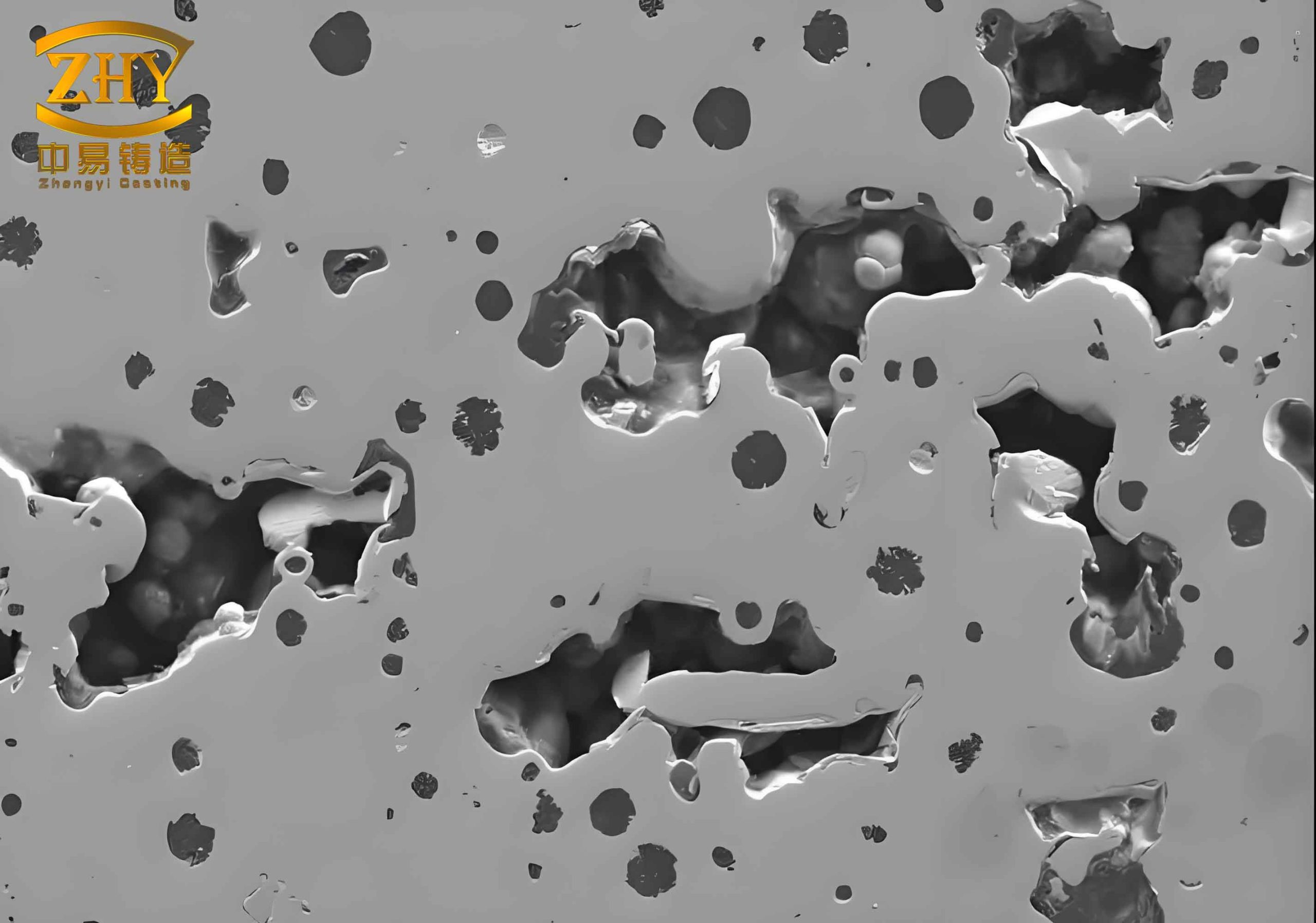
The image above illustrates a typical sand casting defect observed in similar heavy‑section castings. In our case, the shrinkage porosity was concentrated in the thick‑wall region and at the junction between the thick and thin sections, confirming the ineffectiveness of the original feeding strategy.
Simulation Setup
We used AnyCasting to model both the filling and solidification of the original and improved processes. The 3D solid model was created in UG and exported as an STL file. In the AnyPRE environment, a non‑uniform mesh with 4,285,836 elements was generated. The thermal conductivity data for all materials are listed in Table 2, and the process conditions are given in Table 3.
| Material | Thermal conductivity |
|---|---|
| Air | 41.87 |
| Chill (steel) | 3000 |
| Insulating sleeve | 100 |
| Mold (furan resin sand) | 100 |
| Casting (ZG12MnMoV) | Temperature‑dependent |
| Parameter | Value |
|---|---|
| Casting material | ZG12MnMoV |
| Pouring temperature | 1550 °C (improved) / 1580 °C (original) |
| Mold material | Furan resin sand |
| Pouring time | 34 s |
| Pouring nozzle diameter | 55 mm (improved) / 45 mm (original) |
We selected a pure solidification calculation module for defect prediction. The simulation of the original process clearly showed shrinkage porosity in the thick sections, matching the actual scrap parts. The total solidification time and temperature gradient distribution were analyzed to identify the root causes quantitatively.
Theoretical Basis for Shrinkage Formation
Solidification shrinkage occurs in three stages: liquid contraction, solidification contraction, and solid contraction. For cast steel, once the solid skeleton forms, isolated liquid pools remain. Their subsequent contraction without external feed creates voids. The formation of sand casting defect can be described by the Chvorinov’s rule and the modulus concept. The modulus M of a casting section is:
$$
M = \frac{V}{A}
$$
where V is the volume and A is the cooling surface area. Solidification time is proportional to M². To achieve directional solidification, the modulus should increase from the thin to the thick section, leading to the riser. The feeding distance L can be estimated by:
$$
L = M_{\text{riser}} \times k
$$
where k is a factor depending on the alloy and casting geometry (typically 4–6 for steel). In the original design, the modulus of the thickest section (M ≈ 0.067 m) was larger than the riser modulus (M ≈ 0.105 m for the top riser), but the feeding distance was too long because the wall thickness transition interrupted the gradient. The side riser, with a modulus of only 0.055 m, solidified prematurely.
The liquid volume contraction during solidification ε can be expressed as:
$$
\varepsilon = \varepsilon_{\text{liq}} + \varepsilon_{\text{sol}}
$$
For low‑carbon steel, εliq ≈ 1.5% and εsol ≈ 3.5%, giving a total of about 5% volumetric shrinkage. If the riser cannot supply that volume, sand casting defect will form.
Process Improvement
Based on the simulation insights, we modified the casting process as follows:
- Pouring position and parting line: The casting was rotated so that the thickest wall remained at the top, but the overall height of the mold was reduced. The new parting line simplified the molding to a two‑box system, reducing assembly errors.
- Riser and pad design: Two waist‑shaped insulating risers (one open, one blind) were placed at the highest point. To increase the feeding distance, a metal pad (or insulating pad) was added between the casting and the riser, creating a gradual modulus increase. The pad dimensions were determined using the relationship: M_pad = M_section × (1.1 – 1.2). The improvement eliminated the hot‑spot between the riser and the casting.
- Chill placement: Additional external chills were placed at critical thermal nodes to create artificial terminal zones, accelerating cooling and extending the effective feeding distance.
- Pouring temperature: Lowered from 1580 °C to 1550 °C to reduce total shrinkage while maintaining adequate fluidity.
The improved gating system retained the stepped design but enlarged the ingate cross‑section to ensure uniform filling. The pouring nozzle diameter was increased to 55 mm to reduce filling time and prevent premature solidification.
Simulation Results of Improved Process
We reran the AnyCasting simulation with the improved parameters. Figure 2 (simulation) shows the filling sequence: the melt front advanced smoothly without jetting or misruns. The temperature distribution after filling indicated a favorable gradient from the bottom thin sections to the top risers. The solidification simulation predicted no shrinkage porosity or macro‑cavities inside the casting. The hot spots were confined to the risers, confirming that the feeding path remained open until the casting solidified.
The following table summarizes the comparison of the predicted sand casting defect volumes between the original and improved processes:
| Region | Original process | Improved process |
|---|---|---|
| Thick wall (200 mm) | 3.2 % | 0 % |
| Wall transition | 1.8 % | 0 % |
| Lower thin section | 0.5 % | 0 % |
Production Validation
Castings produced with the improved process were fully inspected. Surface quality was excellent—no cracks, sand inclusions, or other visible flaws. Ultrasonic testing according to MC2000 standard confirmed that the internal structure was completely sound, with no indications of shrinkage or porosity. The radiographic examination also passed the strictest criteria for nuclear components. The yield rate increased from below 60% to over 95%, and the machining allowance was reduced because the riser pads were smaller. The improved process not only eliminated sand casting defects but also improved the overall casting quality and production efficiency.
Conclusions
Through this case study, we demonstrated the effectiveness of using AnyCasting simulation to diagnose and eliminate sand casting defect in heavy‑section steel castings. The key contributions are:
- The original three‑box stepped gating system with insufficient riser capacity led to shrinkage porosity. The simulation accurately predicted the defect locations.
- By rotating the casting, adding a properly designed pad and larger risers, and optimizing the chill layout, we achieved directional solidification and eliminated all internal shrinkage.
- Lowering the pouring temperature by 30 °C reduced the total shrinkage while still allowing complete filling.
- The two‑box molding simplified the process and improved dimensional consistency.
- The improved process was validated by actual production, with 100% ultrasonic‑testing acceptance.
This methodology can be extended to other sand castings where sand casting defect due to wall thickness variation is a concern. The combination of thermal modulus analysis and numerical simulation provides a robust tool for process engineers to achieve first‑time‑right castings without costly trial‑and‑error.