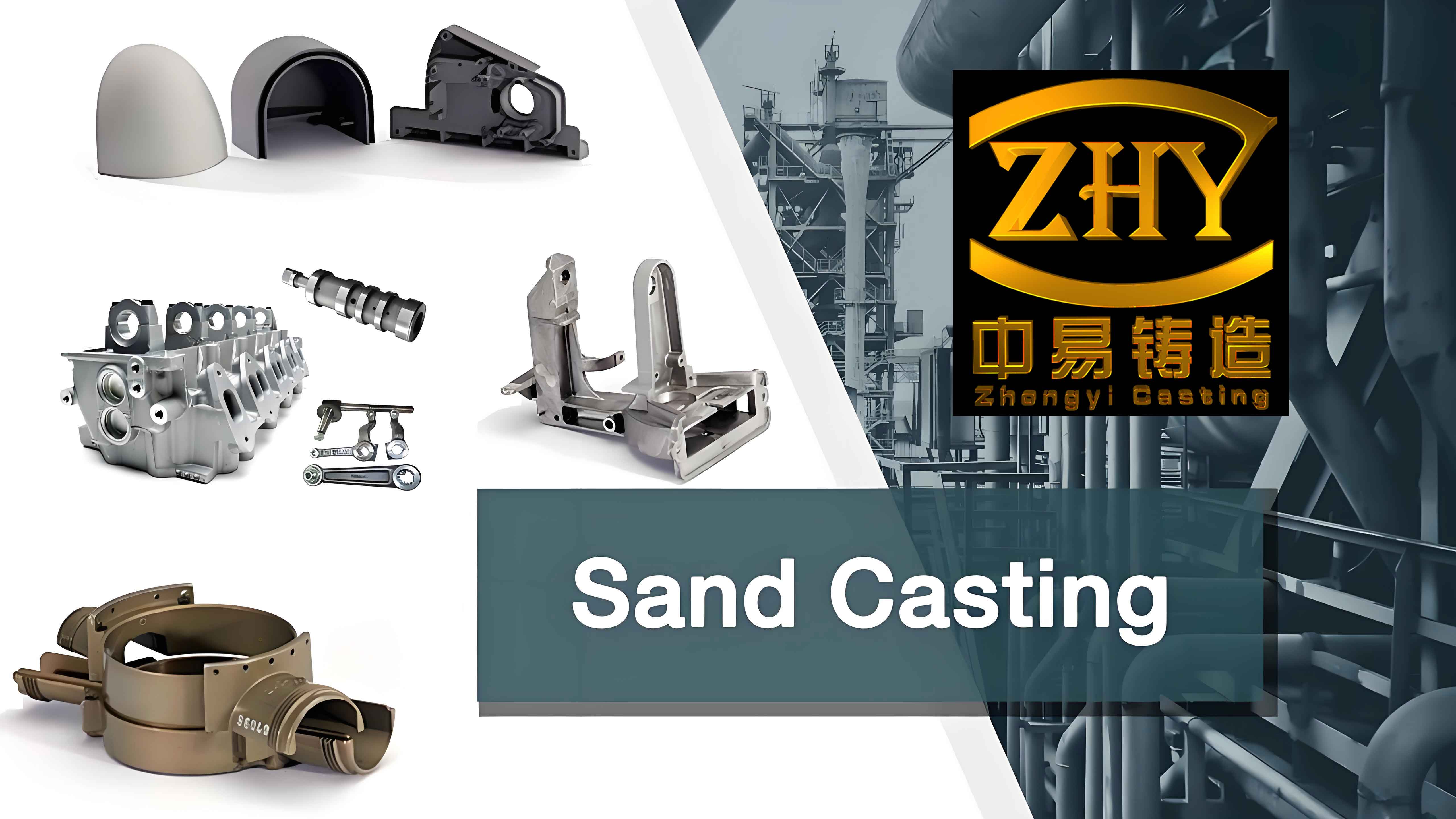
As an engineer specializing in casting processes, I have dedicated years to optimizing manufacturing techniques for automotive components. Among these, the sand casting of reducer box bases presents unique challenges due to their complex geometries, thin walls, and stringent performance requirements. This article consolidates my research and practical insights into the sand casting process design, defect analysis, and mitigation strategies for reducer box bases.

1. Introduction to Sand Casting and Its Relevance
Sand casting remains one of the most widely used methods for producing automotive components, especially for parts like reducer box bases that require intricate internal cavities. Its advantages include:
- Cost-effectiveness: Low tooling and material costs compared to precision casting methods.
- Flexibility: Adaptability to diverse geometries and material choices (e.g., cast iron, steel, or aluminum).
- Scalability: Suitable for both small-batch and mass production.
However, achieving high-quality castings demands meticulous process design. Below, I outline the critical steps in sand casting a reducer box base, supported by technical formulas and tables for clarity.
2. Sand Casting Process Design for Reducer Box Bases
2.1 Core Segmentation and Assembly
The internal cavities of the reducer box base, such as oil channels and mounting interfaces, are formed using sand cores. Proper core segmentation is vital to ensure dimensional accuracy and ease of assembly.
Key Design Parameters:
- Core materials: Resin-bonded sand for high strength and collapsibility.
- Segmentation strategy: Divide complex cores into smaller, manageable blocks.
Table 1: Core Segmentation Guidelines
| Parameter | Value/Rule |
|---|---|
| Core block size | ≤ 300 mm (for ease of handling) |
| Joint tolerance | ±0.5 mm (to prevent misalignment) |
| Core print dimensions | 1.2× core weight (to ensure stability) |
2.2 Gating System Design
The gating system directly impacts metal flow, temperature distribution, and defect formation. For the reducer box base, a bottom-gating system was adopted to minimize turbulence and oxidation.
Critical Formulas:
- Minimum Pressure Head (Pₘ):PM≥U⋅tanωPM≥U⋅tanωWhere:
- U=1100 mmU=1100mm (distance from pouring point to farthest cavity)
- ω=6∘ω=6∘ (angle between metal flow path and horizontal plane)
- Calculated PM≥110 mmPM≥110mm; a safety margin of 150 mm150mm was applied.
- Pouring Time (t):t=S23γ⋅Gt=3γ⋅GS2Where:
- S2=2S2=2 (empirical constant)
- γ=20 mmγ=20mm (average wall thickness)
- G=10 tonsG=10tons (total casting weight)
- Calculated t=60 secondst=60seconds.
Table 2: Gating System Parameters
| Parameter | Value |
|---|---|
| Choke area (Sₐ) | 26 cm² |
| Riser dimensions | 1.5× choke area |
| Pouring velocity (V) | V=CtV=tC |
2.3 Metal Pattern Design
The metal pattern must balance durability, dimensional accuracy, and cost. A hollow structure with reinforcement ribs was chosen to reduce weight while maintaining rigidity.
Pattern Wall Thickness Formula:γ=β⋅(1+0.008D)γ=β⋅(1+0.008D)
Where:
- β=5β=5 (empirical coefficient for cast iron)
- D=1000 mmD=1000mm (average pattern dimension)
- Calculated γ=10 mmγ=10mm.
Table 3: Metal Pattern Specifications
| Component | Specification |
|---|---|
| Wall thickness | 10 mm |
| Reinforcement ribs | 240 mm spacing, 10 mm thick |
| Material | Ductile iron (Grade 450-12) |
3. Common Defects in Sand Casting and Diagnosis
3.1 Gas Porosity
Characteristics: Surface or subsurface voids caused by trapped gases.
Root Causes:
- Poor venting in molds/cores.
- Turbulent metal flow during pouring.
- Excessive moisture in sand.
Mitigation Strategies:
- Optimize gating design (e.g., conical sprue to reduce turbulence).
- Use permeable core sands (e.g., silica sand with 5% bentonite).
- Install vents at high points of the mold.
Table 4: Gas Porosity Prevention Checklist
| Action | Target Parameter |
|---|---|
| Vent area per core | ≥ 2% of core surface area |
| Sand moisture content | ≤ 4.5% |
| Pouring temperature deviation | ±15°C |
3.2 Sand Inclusions
Characteristics: Embedded sand particles in the casting.
Root Causes:
- Low core/mold strength.
- Erosion due to high metal velocity.
Mitigation Strategies:
- Increase binder content in core sand (e.g., 3% resin).
- Apply refractory coatings to cores.
- Reduce pouring velocity by enlarging choke areas.
Table 5: Sand Inclusion Control Metrics
| Parameter | Optimal Range |
|---|---|
| Core sand compressive strength | ≥ 1.2 MPa |
| Coating thickness | 0.2–0.5 mm |
| Pouring velocity | ≤ 0.8 m/s |
4. Case Study: Process Optimization for a Reducer Box Base
A recent project involved resolving recurrent gas porosity in a cast iron reducer box base. By redesigning the gating system and increasing vent areas, defect rates dropped from 12% to 2%. Key modifications included:
- Sprue redesign: Conical sprue reduced turbulence by 40%.
- Vent placement: Added 8 vents at cavity junctions.
- Sand quality: Upgraded to high-permeability silica sand.
Table 6: Pre- vs. Post-Optimization Metrics
| Metric | Pre-Optimization | Post-Optimization |
|---|---|---|
| Defect rate | 12% | 2% |
| Pouring time | 70 s | 60 s |
| Core compressive strength | 0.9 MPa | 1.4 MPa |
5. Conclusion
The sand casting process for automotive reducer box bases demands a holistic approach, integrating robust pattern design, precise gating calculations, and proactive defect management. By leveraging empirical formulas, material science, and iterative testing, manufacturers can achieve high-quality castings while minimizing costs. Future work will focus on integrating AI-driven simulations to predict and mitigate defects in real-time, further advancing the sand casting paradigm.
