
In my research and practice in foundry engineering, I have encountered numerous challenges in producing complex, thin-walled aluminum alloy castings, particularly for structural components like frames. Among these, sand casting remains a versatile and cost-effective method for single-piece or small-batch production of sand casting products. This article details my comprehensive approach to designing and simulating the sand casting process for an aluminum alloy U-shaped outer-ring framework, a component with intricate geometry and stringent quality requirements. The focus is on leveraging traditional sand casting techniques enhanced by modern simulation tools to achieve defect-free sand casting products.
The framework in question, as shown in the image below, is a marine application component requiring high specific strength, dimensional accuracy, and structural integrity. Its design embodies typical difficulties in sand casting products: complex contours, thin walls, and internal cavities with ribs. My objective was to develop a robust sand casting process that mitigates common defects such as shrinkage porosity, cold shuts, oxide inclusions, and distortion, thereby ensuring reliable sand casting products for critical applications.
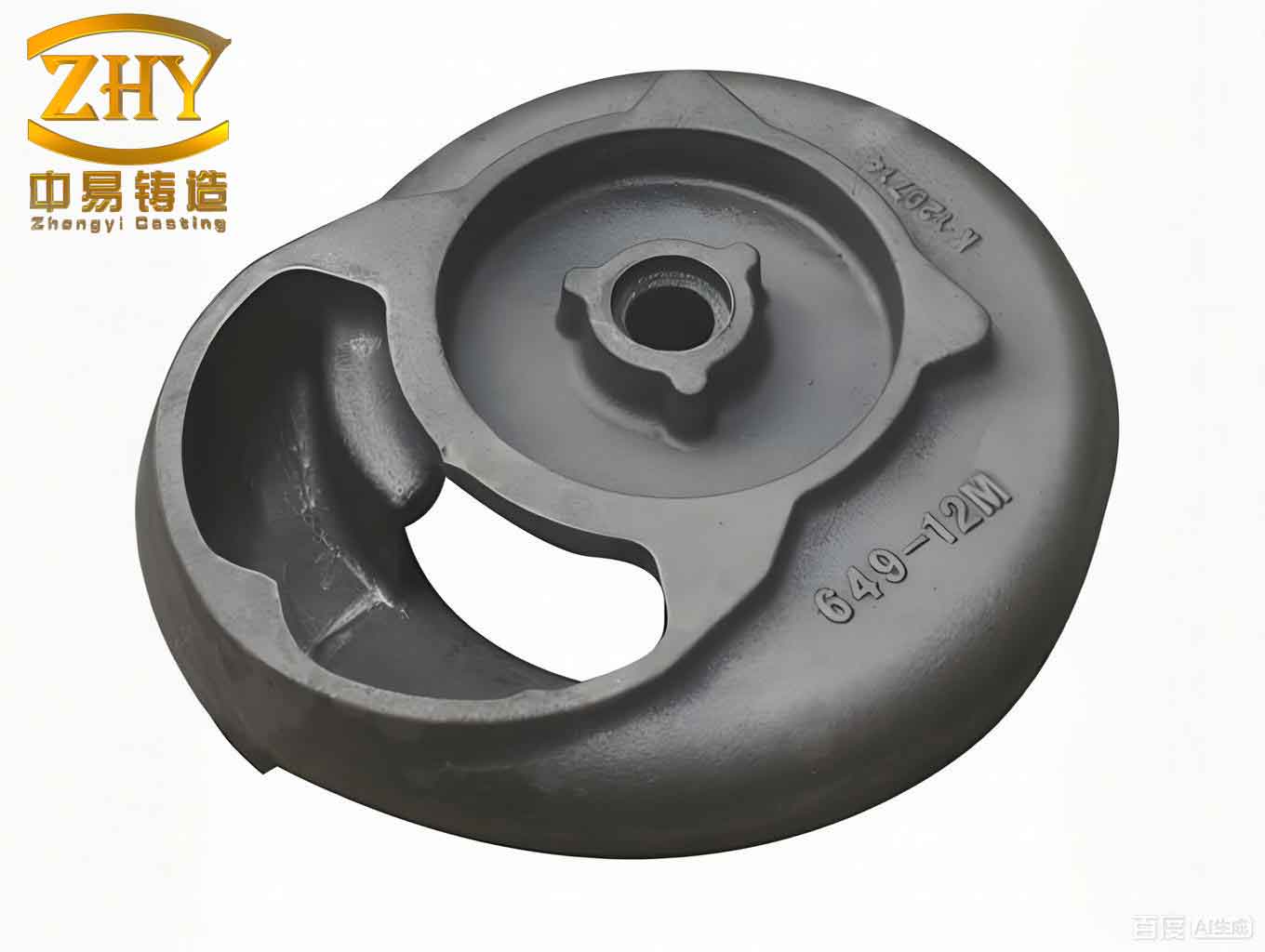
The material specified is ZL114A aluminum alloy, known for its good castability and mechanical properties. The casting’s overall dimensions are 2300 mm in length, 570 mm in width, and 520 mm in height, with an average wall thickness ranging from 12 to 20 mm. Key technical requirements include a casting tolerance grade of CT10, dense microstructure free from shrinkage and gas porosity, and subsequent artificial aging to relieve stresses. Only the central and end surfaces require machining, while numerous small holes on the bottom are to be drilled post-casting due to their size. The internal structure features a flattened, partitioned cavity, making core-making and placement particularly challenging for sand casting products of this nature.
My process design began with a thorough analysis to determine the optimal pouring position and parting plane. Given the casting’s elongated U-shape and the need for simplicity in single-piece production, I positioned the longitudinal axis horizontally. The parting plane was set at the mid-height of the casting, effectively splitting the mold into upper and lower boxes. This two-box molding strategy offers several advantages for sand casting products: it reduces molding height, simplifies pattern making, and facilitates the fabrication and placement of internal cores. The pouring position is at the center of the height, ensuring balanced filling and minimizing turbulence. The schematic representation of this setup is crucial for visualizing the mold assembly.
The core system is fundamental to forming the internal cavities. I designed four distinct sand cores (X1, X2, X3, and X4) to achieve the required geometry. Core X1 forms the central cylindrical cavity and surrounding features, including some small holes, which enhances accuracy and reduces post-casting work. Cores X2 and X3 are mirrored to create the left and right major cavities. Instead of splitting these into separate upper and lower cores—which would compromise rigidity and alignment—I designed each as a single core spanning the parting plane. This design incorporates an integral rib to form the internal partition, ensuring dimensional consistency. However, supporting these large, flat cores was a challenge. My innovative solution involved pre-fabricating six solid aluminum rods of the same alloy (ZL114A), which are cast into the framework. These rods pass through the partition ribs and outer walls, serving a dual purpose: they act as chills to eliminate hot spots and provide mechanical support for cores X2 and X3 during molding. The rods are roughened (with intentional fins) at the interfaces to anchor the sand securely. Additionally, to prevent gas entrapment in the rib areas, I placed 6 mm diameter steel tubes in the upper sections of these cores as vents. Core X4 is dedicated to forming the gating system’s sprue, designed with a necked shape for easy fitting into the pouring cup in the upper mold. This systematic core design is a testament to the precision required in advanced sand casting products.
The gating system is critical for ensuring smooth, controlled filling. For this aluminum alloy casting, minimizing turbulence to prevent oxide formation and slag entrainment is paramount. I adopted a bottom-gating system with a central sprue, symmetrical runners, and multiple ingates. The sprue consists of eight separate channels arranged in a flake-like configuration, each with a cross-sectional area of 2 cm². This design disperses the metal flow, reducing velocity and promoting laminar flow into the mold cavity—a key consideration for high-quality sand casting products. The total cross-sectional areas were calculated based on ensuring adequate flow rate while maintaining an open gating ratio (sprue:runner:ingate) of 1:4:4, which is suitable for aluminum alloys. The calculations are as follows:
Total sprue area: $$\sum A_{sprue} = 8 \times 2 \, \text{cm}^2 = 16 \, \text{cm}^2$$
Total runner area: $$\sum A_{runner} = 4 \times \sum A_{sprue} = 4 \times 16 = 64 \, \text{cm}^2$$ (split into two symmetrical runners, each with area 32 cm²)
Total ingate area: $$\sum A_{ingate} = 4 \times \sum A_{sprue} = 4 \times 16 = 64 \, \text{cm}^2$$ (distributed as 8 ingates, each 8 cm²)
To further enhance slag trapping, I incorporated a ceramic foam filter with a mesh size of 2 mm at the entrance to the runner system. The ingates are positioned evenly along the runners to feed the casting at multiple points, preventing localized overheating and promoting uniform temperature distribution—a vital factor for the integrity of sand casting products.
Riser and chill design is essential for achieving directional solidification and feeding shrinkage. The casting’s modulus (chilling modulus) was calculated to identify hot spots. The average modulus \( M_c \) is 0.93 cm, but critical sections have higher moduli: the side block areas have \( M_{c1} = 1.48 \, \text{cm} \) and the central cylindrical area has \( M_{c2} = 1.87 \, \text{cm} \). Using the principle of directional solidification, I placed risers at these hot spots, supplemented with chills to extend the feeding range. The feeding distance \( L \) for aluminum alloys is approximately \( L = 2T \), where \( T \) is the wall thickness. To optimize this, I employed a combination of insulating risers and external chills. The table below summarizes the riser and chill configuration:
| Location | Riser Type | Dimensions (mm) | Chill Type & Quantity | Chill Dimensions (mm) |
|---|---|---|---|---|
| Side Blocks (Left & Right) | Insulating Side Riser (Dark) | 170 × 80 × 64 (approx. volume) | #1 Chill, 3 pieces per side | 162 × 52 × 30 |
| Central Cylindrical Area | Cylindrical Top Riser (Open) | Diameter: 170, Height: 100 | #2, #3, #4 Chills (conforming shapes) | Varied to fit geometry |
The side risers are placed above the side blocks, with chills positioned below to create a steep temperature gradient. The central riser is located on the top arc surface, fed from the side, and surrounded by conforming chills (#2, #3, #4) at the bottom and sides to ensure sequential solidification toward the riser. This coordinated use of risers and chills effectively prevents shrinkage defects, a common issue in thick sections of sand casting products.
To validate the process design before physical prototyping, I conducted numerical simulation of the filling and solidification processes using advanced casting simulation software. This step is increasingly indispensable for optimizing sand casting products, as it allows for virtual testing and refinement. The simulation parameters included the alloy’s thermophysical properties, initial pouring temperature of 740°C, and the designed gating and feeding system. The filling process simulation revealed a sequential and balanced fill pattern. Metal entered through the multiple ingates, gradually filling the cavity from the bottom upward with minimal turbulence. Temperature distribution during filling showed a gradient: lower regions cooler (around 610°C at fill end) and upper regions warmer, with slightly elevated temperatures near the gates. This pattern indicates controlled flow, reducing the risk of cold shuts and oxide formation—critical for aluminum sand casting products.
The solidification simulation provided insights into the thermal gradients and solidification sequence. As shown in the table below, solidification initiated at the thin walls and extremities, progressing toward the hotter sections and finally the risers. The chills accelerated cooling in targeted areas, effectively extending the feeding range of the risers. The solidification time for the entire casting was sufficiently long to allow adequate feeding, and no isolated liquid pools or hot spots were observed, confirming the efficacy of the riser-chill layout.
| Solidification Stage (%) | Time Elapsed (s) | Key Observations | Temperature Range (°C) |
|---|---|---|---|
| 20 | 45 | Solidification starts at thin walls and bottom edges | 740 – 592 |
| 50 | 120 | Side blocks solidify directionally toward risers; chills active | 666 – 573 |
| 85 | 220 | Central cylinder solidifying; risers remain liquid | 629 – 555 |
| 100 | 310 | Full solidification; no shrinkage defects predicted | 555 (min) |
The simulation results demonstrated that the temperature field aligned with the intended directional solidification, validating the design of the gating system, cores, and feeding mechanism. The absence of predicted defects like shrinkage porosity or cold shuts underscores the robustness of this sand casting process for producing high-integrity sand casting products.
In discussing the broader implications, this case study highlights several best practices for sand casting of complex aluminum frameworks. The use of pre-cast homologous rods is a novel technique that addresses both core support and hot spot elimination, which could be adapted for other sand casting products with internal reinforcements. The flake-type sprue and multi-point ingate system exemplify how gating design can be tailored to reduce turbulence in reactive alloys. Furthermore, the integration of simulation tools enables a data-driven approach to process optimization, reducing trial-and-error and material waste in the production of sand casting products.
From a foundry perspective, the economic and qualitative benefits of such a designed process are significant. For single or small-batch production, the two-box molding minimizes pattern costs and simplifies operations. The strategic use of chills reduces the volume and number of risers, improving yield—a key metric for commercial sand casting products. Moreover, the ensured soundness and dimensional accuracy reduce post-casting rework and scrap, enhancing overall efficiency.
In conclusion, my design and simulation efforts for this aluminum alloy U-shaped framework illustrate a holistic methodology for challenging sand casting products. By carefully selecting the pouring position and parting plane, innovating in core support with integral rods, designing a turbulent-minimizing gating system, and implementing a riser-chill combination for directional solidification, I developed a viable sand casting process. Numerical simulation confirmed its feasibility, predicting defect-free solidification. This approach not only serves the specific component but also provides a template for similar thin-walled, complex aluminum castings, reinforcing the enduring relevance of sand casting in manufacturing high-performance sand casting products. Future work could explore the use of different alloy grades or scale-up for larger sand casting products, further refining these techniques through continuous simulation and experimental validation.