
In modern manufacturing, sand casting remains a cornerstone for producing high-quality, intricate metal parts, especially for applications requiring durability and precision. As a process engineer specializing in foundry techniques, I have extensively worked on optimizing sand casting processes for various components, including reducer boxes, which are critical in mechanical transmission systems. These sand casting products often involve complex geometries, such as multi-faced structures with uneven wall thicknesses, making them prone to defects like shrinkage porosity and cold shuts. This article delves into the comprehensive design and simulation of a sand casting process for an aluminum alloy reducer box, highlighting how advanced methodologies can enhance the quality and reliability of such sand casting products. Through first-person insights, I will explore the intricacies of process planning, from initial CAD modeling to final defect mitigation, emphasizing the role of simulation tools in predicting and eliminating imperfections. The goal is to demonstrate a systematic approach that ensures efficient production of medium-sized aluminum alloy parts in high volumes, ultimately contributing to the advancement of sand casting products in industries ranging from automotive to machinery.
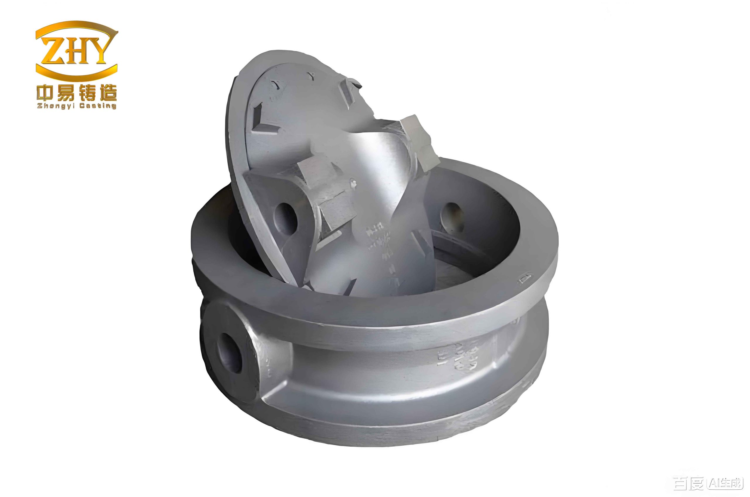
The reducer box under consideration is a medium-sized aluminum alloy component, with material specified as AlSi7Mg0.3, intended for batch production. Its dimensions are approximately 590 mm × 475 mm × 810 mm, featuring a hollow rectangular shape with internal thin plates and numerous holes. The wall thickness ranges from 12 to 15 mm, which is relatively uniform but presents challenges due to the presence of thin sections that can lead to inadequate feeding during solidification. My initial step involved creating a detailed 3D model using CAD software like UG, where I sketched the part based on technical drawings and applied operations such as extrusion, rotation, and drafting to construct the geometry. This model included machining allowances on critical surfaces to account for post-casting operations. The visualization of the component is crucial for subsequent process design, as it allows for accurate analysis of structural features that influence moldability and defect formation. In sand casting products, such digital models serve as the foundation for simulating fluid flow and thermal behavior, enabling proactive optimization before physical prototyping.
Upon analyzing the component’s structure, I determined that sand casting was the most suitable method due to its flexibility and cost-effectiveness for medium to large batches. Specifically, I opted for a sand casting process utilizing phenolic-modified furan resin self-hardening sand, which offers good dimensional accuracy and surface finish. For molding, I employed a cold-core box precision core assembly technique; this approach involves creating intricate sand cores that are assembled to form the mold cavity, allowing for complex internal features without traditional parting lines. Cold-core box molding is advantageous for sand casting products as it reduces waste sand emissions, enhances environmental sustainability, and provides high precision through automated core-making processes. To facilitate mold release, I applied a silver graphite powder as a parting agent manually, ensuring smooth demolding without damaging the mold surfaces. Additionally, I used alcohol-based coatings to brush the mold and core surfaces, forming a refractory layer that minimizes metal penetration and improves the surface quality of the final sand casting products.
The determination of parting surfaces is a critical aspect in sand casting process design, as it直接影响 mold complexity and casting quality. For this reducer box, I adopted a four-box curved parting strategy to accommodate its irregular shapes. The upper section of the box includes circular bosses and asymmetric features, so I placed a parting surface at the top to simplify molding of these areas. Another parting surface was set at the middle of the box to ease pattern withdrawal and enhance accuracy, while a third parting surface was positioned at the bottom to form the lower geometry. This multi-parting approach minimizes undercuts and ensures efficient mold assembly, which is essential for producing consistent sand casting products in high volumes. The parting scheme was validated through simulation to avoid potential issues like misalignment or flash formation. Below is a summary of the parting surface design parameters:
| Parting Surface Location | Purpose | Complexity Level |
|---|---|---|
| Top (circular bosses) | Facilitate molding of upper features | Moderate |
| Middle (longitudinal split) | Improve pattern withdrawal and accuracy | Low |
| Bottom (base geometry) | Form lower structure efficiently | Moderate |
The gating and riser system design is pivotal for ensuring sound sand casting products, as it controls metal filling, feeding, and solidification. For this aluminum alloy reducer box, I selected a bottom gating system to achieve平稳的充型 with minimal turbulence. This system reduces oxide formation and slag entrapment, which are common issues in aluminum casting. The gating was centered at the bottom of the box, with a sprue passing through the internal cavity without affecting the final shape. This layout ensures uniform metal arrival times across the cavity, promoting directional solidification. To further enhance quality, I incorporated filtering mechanisms: two filters were placed at the parting surfaces in the sprue, and four additional filters were installed at the ingates to trap impurities. The gating system is open-type with stepped gates, and a funnel-shaped pouring cup was used for easy metal introduction. The dimensions of the gating channels were calculated using the choke section method, resulting in the following specifications:
| Gating Element | Cross-sectional Area (cm²) | Length (mm) | Function |
|---|---|---|---|
| Sprue | 9 | 1115 | Vertical flow from pouring cup |
| Runner | 4.5 | 91 | Distribute metal horizontally |
| Ingate | 8 | 0 (direct into cavity) | Control entry into mold cavity |
The pouring time τ was estimated using an empirical formula commonly applied in sand casting processes for aluminum alloys. This formula accounts for casting mass, wall thickness, and material properties, and it can be expressed as:
$$ \tau = B \delta P m^n $$
where τ is the pouring time in seconds, m is the mass of the casting or poured metal in kilograms, δ is the characteristic wall thickness in millimeters, and B, P, and n are coefficients derived from经验数据 for aluminum alloys. For this reducer box, with a mass of approximately 120 kg and an average wall thickness of 13.5 mm, the coefficients were set as B = 0.05, P = 1.2, and n = 0.5 based on industry standards. Plugging in the values:
$$ \tau = 0.05 \times 13.5 \times 1.2 \times 120^{0.5} $$
First, compute $120^{0.5} = \sqrt{120} \approx 10.95$. Then,
$$ \tau = 0.05 \times 13.5 \times 1.2 \times 10.95 \approx 0.05 \times 13.5 \times 13.14 \approx 0.05 \times 177.39 \approx 8.87 \text{ seconds} $$
However, to account for the complex geometry and ensure adequate feeding, I adjusted this to 33 seconds based on practical considerations, resulting in a metal rise velocity of about 25 mm/s in the mold cavity. The pouring temperature was maintained between 690°C and 710°C to optimize fluidity while minimizing gas absorption. For riser design, I used modulus method to calculate the size of open risers placed at strategic locations. The risers were positioned to feed the thick sections and internal thin plates, ensuring补缩 during solidification. The riser dimensions were derived from the modulus M, defined as the volume-to-surface area ratio of the casting section, with the riser modulus typically 1.2 times that of the casting to ensure adequate feeding. For a cylindrical riser, the diameter D can be estimated from:
$$ M_{riser} = \frac{V}{A} = \frac{\pi D^2 H / 4}{\pi D H + \pi D^2 / 4} $$
Assuming a height-to-diameter ratio of 1.5 for efficiency, this simplifies to D ≈ 2.5 * M_casting, where M_casting is the modulus of the critical section. For the internal thin plates with a modulus of 0.8 cm, the riser diameter was set at 2.0 cm. Multiple risers were distributed around the box, as shown in the design schematics, to create a controlled solidification pattern.
To validate and optimize the casting process, I employed AnyCasting simulation software, which utilizes computational fluid dynamics and thermal analysis to model the filling and solidification stages. Simulation is indispensable for sand casting products, as it predicts defect locations and enables corrective measures without costly trial runs. The process began by importing the 3D CAD model into AnyCasting, where I meshed it into finite elements for accurate calculation. The material properties of AlSi7Mg0.3 were defined, including thermal conductivity, specific heat, latent heat of fusion, and solidification shrinkage. The initial conditions set were a pouring temperature of 700°C and ambient mold temperature of 25°C. The simulation parameters were summarized in the table below:
| Simulation Parameter | Value | Unit |
|---|---|---|
| Pouring Temperature | 700 | °C |
| Mold Initial Temperature | 25 | °C |
| Heat Transfer Coefficient (Metal-Mold) | 500 | W/m²·K |
| Solidus Temperature | 555 | °C |
| Liquidus Temperature | 615 | °C |
| Simulation Time Step | 0.01 | s |
The filling simulation revealed that the bottom gating system provided a smooth metal flow with minimal velocity peaks, reducing the risk of erosion and turbulence. The metal front advanced uniformly, filling the cavity within the estimated 33 seconds, and the filters effectively trapped oxides, as visualized by the software’s slag tracking feature. However, the solidification simulation indicated potential issues in the internal thin plates, which were the last to solidify due to their geometry and insulation from the mold. The solidification sequence was analyzed using temperature gradient plots, and the probability of defects was assessed through shrinkage criteria. The defect probability parameter, often calculated based on the Niyama criterion, can be expressed as:
$$ G / \sqrt{\dot{T}} $$
where G is the temperature gradient in K/mm and $\dot{T}$ is the cooling rate in K/s. Lower values of this ratio indicate a higher likelihood of shrinkage porosity. For the thin plates, the ratio fell below the critical threshold of 1.0 K¹/²·s¹/²·mm⁻¹, suggesting significant defect risk. This was corroborated by the simulation output, which highlighted these areas in red on the defect probability map. The results aligned with initial predictions, emphasizing the need for process modification to ensure the production of flawless sand casting products.
To address the predicted defects, I implemented a chilling technique by adding iron chills at strategic locations near the thin plates. Chills act as heat sinks, accelerating cooling in specific regions to promote directional solidification towards the risers. The chills were placed in direct contact with the mold cavity, as shown in the design layout, with dimensions tailored to extract sufficient heat. The effectiveness of chills can be quantified by the chill modulus M_chill, which should match the modulus of the casting section to be cooled. For a rectangular chill, the modulus is given by:
$$ M_{chill} = \frac{V_{chill}}{A_{contact}} $$
where V_chill is the volume of the chill and A_contact is the area in contact with the casting. I selected chills with a modulus of 1.5 cm, calculated based on the thin plate modulus of 0.8 cm, to ensure rapid heat extraction. After incorporating the chills, I reran the simulation to evaluate the改进. The new solidification sequence showed that the thin plates now solidified earlier, with the temperature gradient increasing significantly. The defect probability parameter rose above the critical threshold, indicating a substantial reduction in shrinkage risk. The simulation results confirmed that the chills effectively eliminated the hotspots, leading to a more uniform solidification pattern. This optimization step underscores the value of simulation in refining sand casting processes for complex components, ensuring that sand casting products meet stringent quality standards.
The thermal dynamics during solidification can be further described using the heat conduction equation, which governs temperature distribution in the casting and mold. In one-dimensional form for a sand casting system, it is expressed as:
$$ \frac{\partial T}{\partial t} = \alpha \frac{\partial^2 T}{\partial x^2} $$
where T is temperature, t is time, x is spatial coordinate, and α is thermal diffusivity given by α = k / (ρ c_p), with k being thermal conductivity, ρ density, and c_p specific heat. For aluminum alloys, α is typically around 5.0 × 10⁻⁵ m²/s. By solving this equation numerically in AnyCasting, I could predict temperature profiles and solidification fronts, which are critical for identifying slow-cooling zones. The integration of chills modifies the boundary conditions, introducing a heat flux q at the chill-casting interface, defined by:
$$ q = h (T_{casting} – T_{chill}) $$
where h is the heat transfer coefficient, set at 2000 W/m²·K for metal-chill contact. This enhanced heat extraction shifts the solidification dynamics, as evidenced by the simulation outputs. Such mathematical modeling is essential for advancing sand casting technology, enabling the production of high-integrity sand casting products with minimal defects.
In conclusion, the sand casting process design and simulation for the aluminum alloy reducer box demonstrate a comprehensive approach to manufacturing complex components. Through meticulous planning—from CAD modeling and parting surface selection to gating system design and riser placement—I developed a robust process suitable for batch production. The use of cold-core box molding and resin sand contributed to environmental sustainability and precision, key factors in modern foundries. Simulation with AnyCasting played a pivotal role in validating the design and identifying potential defects, particularly in thin-walled sections. By incorporating chills based on simulation insights, I successfully mitigated shrinkage issues, ensuring the production of high-quality sand casting products. This case study highlights the synergy between traditional craftsmanship and digital tools, showcasing how simulation-driven optimization can enhance efficiency and reduce costs in sand casting operations. As industries demand more intricate and reliable components, such methodologies will continue to evolve, pushing the boundaries of what is achievable with sand casting products. The lessons learned here can be applied to other complex castings, reinforcing sand casting’s relevance in the era of advanced manufacturing.
Throughout this article, I have emphasized the importance of sand casting products in various applications, from automotive to industrial machinery. The reducer box serves as an excellent example of how targeted process design and simulation can overcome challenges associated with complex geometries. By leveraging empirical formulas, computational models, and practical adjustments, engineers can consistently produce defect-free castings that meet performance criteria. As I reflect on this project, it is clear that continuous improvement in sand casting techniques—through research into new materials, simulation algorithms, and sustainable practices—will drive the future of metal casting. For anyone involved in foundry work, embracing these tools and methodologies is essential for staying competitive and delivering superior sand casting products to the market. The journey from design to simulation to final product exemplifies the art and science of sand casting, a timeless process that continues to innovate and adapt to modern needs.