
In my extensive experience within the foundry industry, I have consistently sought advanced methodologies to address persistent casting defects such as internal shrinkage, porosity, and leakage, particularly in complex components like cylinder heads and connecting sleeves used in mining and engineering machinery. Traditional green sand molding processes often fall short, leading to compromised part integrity under high pressure and load conditions. It is through the adoption and refinement of sand coated iron mold casting that I have witnessed transformative improvements in casting quality, dimensional accuracy, and production efficiency. This process, characterized by its rapid heat dissipation, uniform solidification, and rigid mold structure, effectively eliminates the self-feeding shrinkage tendencies inherent in conventional methods. In this article, I will delve into the intricacies of sand coated iron mold casting, exploring material selection, equipment design, production line orchestration, and performance outcomes, all from a first-hand perspective. The integration of tables and formulas will help encapsulate key data and theoretical underpinnings, providing a robust resource for practitioners.
The foundational element of sand coated iron mold casting is the resin-coated sand. This material, composed of calcined sand grains (typically 50-75 mesh) blended with approximately 5% furan resin, exhibits thermal curing properties, excellent flowability under pressure, rapid polymerization, low gas evolution, high thermal resistance, minimal expansion, and good collapsibility at elevated temperatures. Selecting the appropriate grade is critical and depends on the casting’s geometric and thermal characteristics. For instance, thicker, more massive castings demand coated sand with high bending strength, moderate thermal expansion, and controlled loss on ignition and gas emission. In my applications, for cylinder liner castings weighing under 20 kg, I have opted for a cost-effective, high-strength, low-gas type. The table below summarizes typical specifications and performance indicators for various resin-coated sand grades used in sand coated iron mold casting.
| Grade Name | Brand | Specification (AFS) | Cold Bending Strength (MPa) | Hot Bending Strength (MPa) | Thermal Expansion Rate (%) | Loss on Ignition (%) | Gas Evolution (ml/g) | Melting Point (°C) |
|---|---|---|---|---|---|---|---|---|
| Ordinary Type | FMS-PT | 30QH (36-50AFS), 21QH (50-59AFS), 15QH (60-78AFS), 10QH (80-110AFS) | 4.0~7.0 | 2.5~4.0 | ≤1.4 | ≤4.0 | 14~18 | 98±5 |
| High Strength Low Gas | FMS-GQ1 | – | 4.5~7.5 | 3.0~4.2 | ≤1.2 | ≤3.0 | 8~14 | 98±5 |
| High Strength Low Expansion Low Gas | FMS-GQ2 | – | 4.5~8.0 | 3.0~4.5 | ≤0.9 | ≤2.0 | 6~12 | 98±5 |
| High Temperature Resistance Low Expansion | FMS-NW1 | – | 6.5~7.5 | 3.8~4.2 | ≤0.4 | ≤3.5 | 14~18 | 100±5 |
| High Temperature Resistance Low Expansion Low Gas | FMS-NW2 | – | 6.5~8.0 | 3.8~4.5 | ≤0.6 | ≤2.5 | 8~14 | 98±5 |
| Easy Collapse Low Gas | FMS-YK | – | 4.0~5.5 | 2.0~3.2 | ≤1.0 | ≤2.0 | 6~12 | 98±2 |
| High Strength Easy Collapse Low Gas Low Expansion | FMS-GK | – | 4.5~6.0 | 2.8~3.5 | ≤0.8 | ≤2.0 | 6~12 | 98±2 |
| Centrifugal Casting High Strength Low Expansion Low Gas | FMS-LG | – | 3.0~5.0 | 2.0~3.0 | ≤0.7 | ≤2.0 | 6~10 | 98±5 |
| Centrifugal Casting High Temperature Resistance Low Expansion | FMS-LN | – | 3.5~5.5 | 2.5~3.2 | ≤0.4 | ≤2.0 | 7~10 | 100±5 |
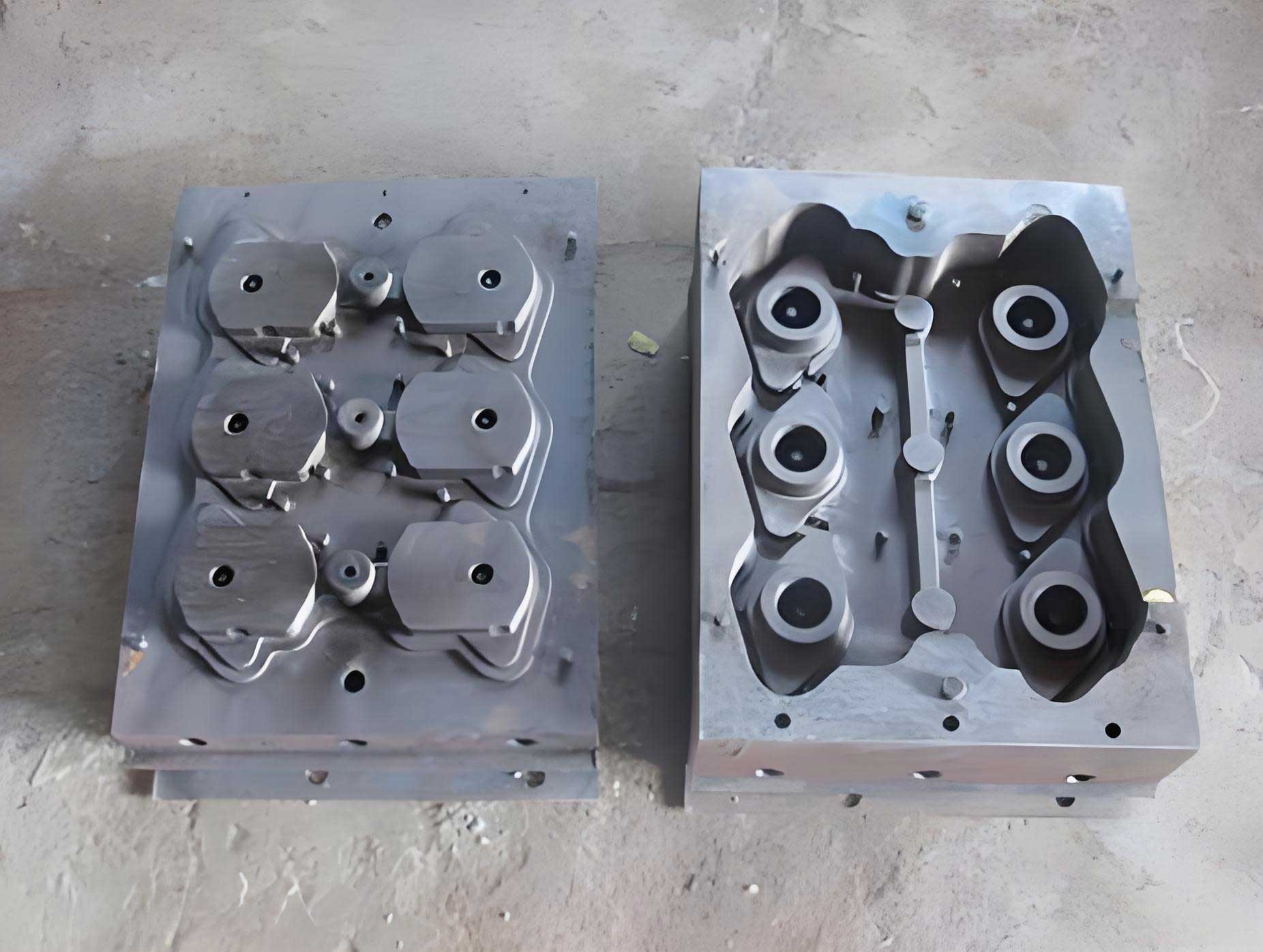
The iron mold itself is a critical component in sand coated iron mold casting. I typically specify molds made from HT200 grade iron, subjected to stress relief annealing and milled flat on both sides. The mold cavity is machined to match the external contour of the casting, and sand injection holes are strategically placed at the highest points of the pattern to ensure complete cavity filling. The thickness of the coated sand layer is usually between 6 mm and 8 mm, optimized based on casting size and thermal requirements. A crucial design principle I adhere to is that the weight of the iron mold should be approximately 7 to 10 times the weight of the cast piece it produces. This ratio ensures sufficient thermal mass to promote rapid, uniform solidification—a hallmark of sand coated iron mold casting—while maintaining mold durability. For example, in producing cylinder liners, the combined weight of the cope and drag molds I use is around 560 kg.
Pattern design and layout are paramount in sand coated iron mold casting. Patterns must be metallic, preferably ductile iron, to withstand cyclic heating during production. Machined to a surface roughness of Ra 1.6 and with a draft angle of 5° to 6°, they facilitate easy stripping after sand curing. The arrangement of patterns on the mold plate must ensure uniform heat distribution and high yield. Symmetrical placement around a central gating system is my preferred approach, as it aids in sand flow during injection, balanced solidification, and simplifies post-casting cleaning. This layout also minimizes thermal distortion of the iron mold, extending its service life. The gating system is integrated to allow simultaneous shot blasting of the casting and the runner, enhancing operational efficiency.
The production line for sand coated iron mold casting is relatively streamlined, predominantly powered by compressed air with minimal electrical controls outside the melting furnace. The core equipment is the sand shooting machine. The process cycle can be described in six distinct steps. First, the pouring step involves filling the prepared molds with treated molten iron. Solidification in sand coated iron mold casting is rapid; typically, the pouring cup is removed within 5 to 8 minutes. Second, after 30 to 50 minutes (depending on casting weight), the mold is opened in the shakeout step, and the casting is ejected. Third, the residual burned sand is removed from the mold via a vibration shakeout machine. Fourth, the cleaning step involves manual removal of any adhering sand or iron beads from the mold cavity and optional cooling if mold temperature is excessive. Fifth, the cleaned mold enters the molding step, where resin-coated sand is injected into the preheated (around 300°C) mold cavity. The sand quickly cures, and the pattern is stripped within about 3 minutes. Sixth, in the closing step, any necessary cores are set, floating sand is blown off, and the molds are closed with a 0.6 mm to 0.8 mm spacer to prevent core crushing and aid venting. The closed mold then returns to the pouring line, completing the cycle.
Several process parameters demand meticulous attention in sand coated iron mold casting. Resin-coated sand must be stored under dry, cool conditions to prevent moisture absorption and pre-curing. To combat veining defects, additives like 0.3% to 0.6% organic compounds or 0.15% to 1.0% iron oxide red can be blended into the sand. The iron mold must be retired if the sand layer becomes too thin, or if the mold deforms or cracks. Pattern temperature regulation is vital; maintaining it at 300°C ensures optimal sand flow and easy demolding. A mold release agent, such as lycopodium powder or a commercial spray, should be applied periodically—for instance, after every five shots. Synchronizing the melting rate with the molding pace is essential. I generally set the furnace melting rate slightly higher than the molding line’s capacity, allowing the molten iron to hold for about 10 minutes. This facilitates slag separation, yielding cleaner iron. Pouring temperature control is another critical factor. For ductile iron castings like QT450-10, I aim for a tapping temperature of 1490°C, followed by spheroidizing and inoculation. Pouring begins at 1430°C and should not drop below 1400°C. The iron mold temperature must be monitored with an infrared pyrometer; if it exceeds 300°C, forced cooling is necessary to maintain sand injection quality and prevent sand burning, which can cause casting defects. The demolding time after pouring is set around 30 minutes, balancing casting hardness and production cycle.
The superiority of sand coated iron mold casting is quantitatively evident in metallurgical and mechanical properties. For cylinder liner components requiring QT450-10 material, this process consistently yields finer graphite structures and enhanced mechanical performance compared to conventional green sand casting. The table below presents a comparative analysis from my work, highlighting the benefits of sand coated iron mold casting.
| Process Category | Sample | Spheroidization Grade | Graphite Grade | Tensile Strength (MPa) | Elongation (%) |
|---|---|---|---|---|---|
| Conventional Green Sand Casting | 1 | 3 | 4 | 390 | 9.2 |
| 2 | 3 | 4 | 410 | 8.1 | |
| 3 | 3 | 4 | 420 | 9.0 | |
| 4 | 3 | 4 | 407 | 9.1 | |
| 5 | 3 | 4 | 420 | 9.7 | |
| Sand Coated Iron Mold Casting | 1 | 2 | 3 | 450 | 10.0 |
| 2 | 2 | 3 | 453 | 11.1 | |
| 3 | 2 | 3 | 457 | 12.2 | |
| 4 | 2 | 3 | 460 | 10.0 | |
| 5 | 2 | 3 | 455 | 11.1 |
The fundamental advantage of sand coated iron mold casting lies in its thermal dynamics. The chill effect of the iron mold combined with the thin, insulating sand layer promotes a near-simultaneous solidification, reducing thermal gradients that lead to shrinkage porosity. This can be conceptualized using solidification models. The solidification time for a casting can be approximated by Chvorinov’s rule:
$$t = k \left( \frac{V}{A} \right)^n$$
where \(t\) is the solidification time, \(V\) is the casting volume, \(A\) is its surface area, \(k\) is a mold constant, and \(n\) is an exponent (typically around 2 for many conditions). In sand coated iron mold casting, the mold constant \(k\) is significantly lower than in green sand due to the higher thermal conductivity of the iron mold, leading to much shorter solidification times. This rapid solidification suppresses the formation of coarse graphite and shrinkage cavities. Furthermore, the pressure exerted by the rigid mold during graphite expansion phases can be analyzed. The internal pressure \(P_i\) due to graphite precipitation can be partially counteracted by the mold’s resistance, reducing mold wall movement. A simplified force balance can be expressed as:
$$P_i \cdot A_c \leq \sigma_y \cdot A_m$$
where \(P_i\) is the internal pressure from expansion, \(A_c\) is the effective area of the casting face, \(\sigma_y\) is the yield strength of the mold material, and \(A_m\) is the load-bearing cross-section of the mold. The iron mold’s high strength in sand coated iron mold casting ensures this inequality holds, minimizing dimensional inaccuracies.
Temperature management during the cycle is another area where formulas provide insight. The cooling of the iron mold after pouring can be modeled approximately using Newton’s law of cooling:
$$T_m(t) = T_{env} + (T_{pour} – T_{env}) e^{-ht}$$
where \(T_m(t)\) is the mold temperature at time \(t\), \(T_{env}\) is the ambient temperature, \(T_{pour}\) is the initial mold temperature after pouring, and \(h\) is a heat transfer coefficient specific to the mold design and cooling conditions. In practice, for sand coated iron mold casting, I monitor \(T_m(t)\) to ensure it stays below 300°C before the next sand shooting cycle to maintain process stability.
In application, sand coated iron mold casting has proven exceptionally effective for parts with non-uniform wall thickness and intricate internal passages, such as oil galleries and reservoirs in cylinder heads. The process eliminates micro-shrinkage in these critical zones, thereby preventing leakage under high pressure—a common failure mode in green sand castings. The aesthetic quality is also superior, with castings requiring minimal finishing and having virtually no flash, thanks to the precision of the rigid mold. This translates to reduced cleaning labor and higher overall productivity. The success in cylinder liners has led to the adoption of sand coated iron mold casting for a broader range of components, including diesel engine parts, reducer housings, and various engineering machinery castings.
Looking at the broader context, sand coated iron mold casting represents a sustainable advancement. While traditional green sand processes generate substantial waste sand, this method uses a consumable sand layer that is orders of magnitude thinner, reducing sand consumption and waste generation per casting. The iron mold is reusable for thousands of cycles, amortizing its initial cost. The energy efficiency is also notable; the rapid cycling reduces holding times for molten metal, and the superior casting yield lowers the total metal required per finished part.
In conclusion, from my firsthand involvement, sand coated iron mold casting stands as a robust solution for high-integrity castings. Its synergy of a rigid iron mold and a thin, precisely applied resin-coated sand layer facilitates rapid, uniform solidification, yielding fine microstructures (graphite grades 1-3), excellent mechanical properties, and exceptional surface finish. The process control, from sand selection to temperature management and production line synchronization, is key to its success. The comparative data unequivocally demonstrates its superiority over conventional green sand methods in mitigating internal defects and enhancing performance. As industries demand lighter, stronger, and more reliable components, sand coated iron mold casting will undoubtedly continue to expand its application footprint, driven by its technical merits and economic benefits. Further research could focus on optimizing sand formulations for even lower emissions and developing more sophisticated thermal models to predict solidification patterns in complex geometries using this versatile process.