
In the design of shell mold, the feeding of molten iron of nodular iron and the solution of casting defects such as internal shrinkage porosity and shrinkage cavity are mainly considered. Therefore, the following aspects are considered in the design:
(1) concealed riser design:
A. Theoretical calculation:
The theoretical weight of riser is:
Riser weight (risen WT) = casting weight / 6.5 + R3 / 25 (kg) (r riser radius)
Through theoretical calculation, the required riser weight and volume of S1100 diesel engine crankshaft are as follows: riser weight: 4.25kg; Riser volume: 574ml. Weight and volume of crankshaft casting: riser weight ratio volume = 3.88:1.
B. This design:
In the design, because it is considered as a concealed riser, there is a certain static pressure in feeding. Therefore, in order to improve the casting yield and reduce the design size of the riser, the design size of the concealed riser is shown in Figure 1:
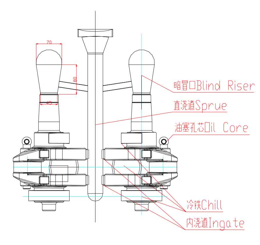
Crankshaft casting weight: 16.5kg, volume: 2.23cm3;
Weight of concealed Riser: 2.49kg, volume: 0.34cm3; The ratio of casting wt & risen WT is 6.6:1.
(2) design of sprue and internal sprue:
For crankshaft castings with vertical pouring and vertical cooling process, the bottom pouring process is widely used in the design of sprue. Through the structural analysis of the crankshaft of S1100 diesel engine, because the crankshaft has a large oil plug hole (with oil plug hole core inside) at the connecting rod journal, it is easy to block the molten iron during pouring. Therefore, it is changed to feed molten iron at the two fan plates of the crankshaft. At the same time, in order to avoid the molten iron temperature of the end dark riser being lower than that of the casting and reduce the feeding effect, a molten iron connection channel is set near the dark riser in the sprue. The cross-sectional area of the inner sprue is smaller than that of the fan plate, so that the solidification of the inner sprue is prior to that of the sprue. When cooperating with the cold iron at the fan plate, avoid the graphitization expansion at the fan plate from expanding to the sprue, resulting in shrinkage porosity and shrinkage cavity at the fan plate. At the same time, it is convenient to separate the casting from the sprue during cleaning. The specific parameters of the gating system are:
A sprue diameter is Φ 35mm;
B. two internal gates per piece 15 × 20mm2;
C. the head of gate cup to riser of casting is 30mm;
D. weight of gating system: 40kg.
(3) setting of cold iron:
In order to speed up the cooling speed, it is necessary to adopt the forming cold iron process and forced fast cooling. The setting of cold iron is the key to solve the casting defects of shrinkage porosity and shrinkage cavity caused by the feeding difficulty of crankshaft, especially most of its thick molten iron. Setting principle of cold iron: in the hot spot where heat dissipation is difficult, appropriate measures shall be taken to strengthen the cooling of the casting surface, so as to solidify the crust on the hot spot surface as soon as possible, so as to prevent shrinkage and looseness caused by the expansion of its shape. After analysis, it is very possible to have shrinkage casting defects at the thick parts of the crankshaft main journal and fan plate. Therefore, two kinds of cold irons are set at the crankshaft main journal and fan plate.
Cold iron at fan plate (see Figure 2 below):
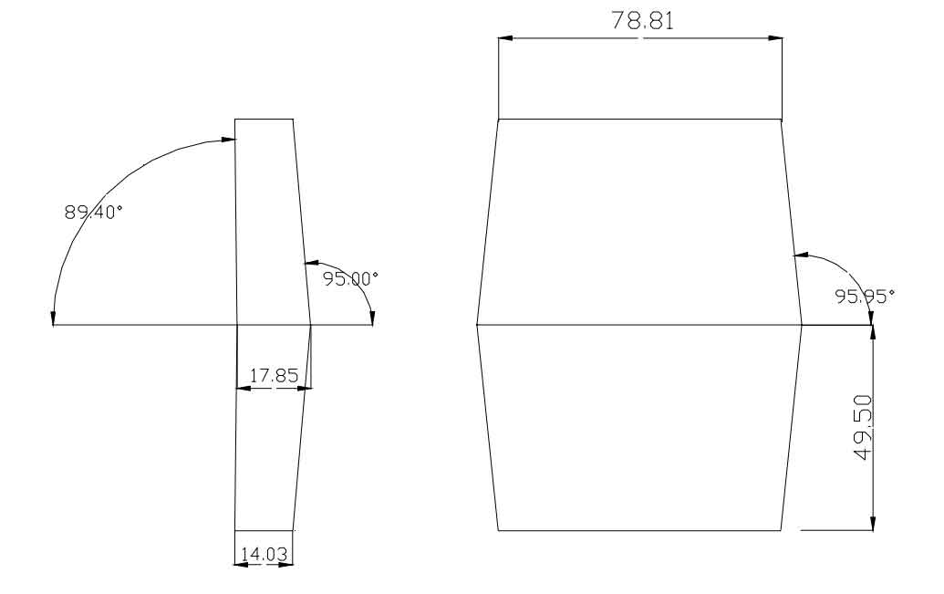
The connection between the fan plate and the connecting rod journal is the thickest part of the crankshaft. When the connecting rod journal has an oil plug clay core to block the feeding of molten iron at the upper part, the casting defects of shrinkage porosity and shrinkage cavity are most likely to occur at the connection between the fan plate and the connecting rod journal. Therefore, wedge-shaped cold iron blocks are set here. In order to avoid premature solidification and cooling of molten iron in the inner sprue by the cold iron block, the cold iron block is arranged near the connecting rod journal (as shown in Figure 1).
At the crankshaft journal (see Figure 3):
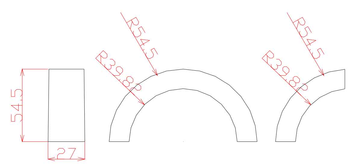
In order to facilitate the removal of the cold iron at the main journal during cleaning, the cold iron is designed into three combined cold irons (as shown in Figure 3: 1 / 2 and 1 / 4 combined structure). The cold iron thickness is 15mm and the width is 27mm.