
As an engineer specializing in casting technology, I embarked on designing an efficient shell casting process for a gear oil pump housing, focusing on overcoming common defects like shrinkage, cold cracks, and misruns. Shell casting is pivotal in industries requiring precision components, such as automotive and petroleum sectors, where gear oil pumps ensure reliable fluid transfer. The housing, made of HT200 gray iron, demanded meticulous attention to its compact, hollow structure with wall thicknesses ranging from 6 mm to 25 mm. Through iterative analysis and simulation, I developed a robust methodology to enhance casting yield and quality, emphasizing the shell casting approach for its cost-effectiveness and adaptability.
Initial analysis of the gear oil pump shell casting revealed several challenges. The housing’s intricate geometry included internal cavities and reinforcing ribs, which complicated mold separation and risked defects like hot tears. Minimum wall thickness was 6 mm, exceeding the 3–4 mm limit for sand casting but still prone to thermal stresses. I selected wet sand casting for its operational simplicity and low cost, using refractory clay sand to handle the high fluidity and shrinkage of gray iron. Key issues identified were: difficulty in forming small holes (e.g., 4×M8-6H holes) due to thick sections, requiring post-casting machining; uneven wall distribution leading to potential cracking; and large parting planes increasing inclusion risks. To address these, I prioritized a shell casting process with optimized gating, risers, and chills.
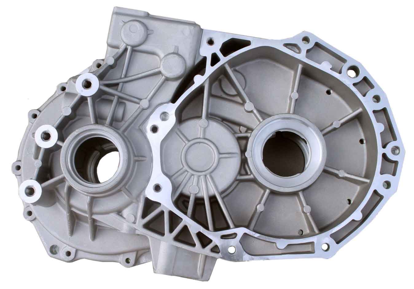
For the shell casting process design, I began with parting surface selection to facilitate core placement and mold assembly. A horizontal parting plane along the housing’s mid-section enabled easy pattern withdrawal and minimized sand cores, as illustrated in the figure. Draft angles were calculated using the incremental thickness method, yielding $$ \alpha_{\text{draft}} = 1^\circ 25′ $$ and an incremental value of 1 mm per side. This ensured smooth demolding while maintaining dimensional accuracy within CT11-CT14 tolerances, with a machining allowance of 2 mm. The gating system was designed as a closed type with intermediate pouring to ensure steady filling. Calculations started with determining the casting’s mass: total volume included the housing and excluded non-cast holes, leading to $$ V_{\text{total}} = V_{\text{casting}} + V_{\text{holes}} = 316.02 \, \text{cm}^3 + 6.28 \, \text{cm}^3 = 322.3 \, \text{cm}^3 $$. With gray iron density $$ \rho = 6.8 \, \text{g/cm}^3 $$, mass was $$ M = \rho V_{\text{total}} = 2.191 \, \text{kg} $$. For two castings per mold, total mass became $$ M_{\text{total}} = 4.382 \, \text{kg} $$.
Pouring time was derived from empirical relations: $$ t = S_1 M_{\text{total}}^{0.5} $$, where $$ S_1 = 2 $$ for medium wall thickness. This gave $$ t = 2 \times (4.382)^{0.5} = 4.1866 \, \text{s} $$, rounded to 5 s for safety. Flow coefficient $$ \mu = 0.45 $$ was selected based on standard tables. Average pressure head $$ H_p $$ was calculated as $$ H_p = H_0 – \frac{C}{8} $$, with $$ H_0 = 7.2 \, \text{cm} $$ and $$ C = 6.4 \, \text{cm} $$, resulting in $$ H_p = 6.4 \, \text{cm} $$. The minimum choke area, set at the ingate for a closed system, was computed using: $$ A_{\text{choke}} = \frac{M_{\text{choke}}}{0.31 \mu t \sqrt{H_p}} $$. Substituting values: $$ A_{\text{choke}} = \frac{4.382}{0.31 \times 0.45 \times 5 \times \sqrt{6.4}} = 2.48 \, \text{cm}^2 $$. Gating ratios were fixed at $$ \sum A_{\text{ingate}} : \sum A_{\text{runner}} : \sum A_{\text{sprue}} = 1 : 1.2 : 1.4 $$, yielding ingate area $$ A_{\text{ingate}} = 2.48 \, \text{cm}^2 $$, runner area $$ A_{\text{runner}} = 2.976 \, \text{cm}^2 $$, and sprue area $$ A_{\text{sprue}} = 3.472 \, \text{cm}^2 $$. Standard dimensions were referenced, with ingates sized at 24 mm × 21 mm × 10 mm, runners at 17 mm × 12 mm × 21 mm, and sprue at bottom diameter 21 mm, top diameter 30 mm, height 72 mm. A sprue well was incorporated to reduce turbulence, designed as a concave pocket below the sprue.
Riser and chill design in the shell casting process targeted shrinkage compensation and thermal management. Using the sectional proportionality method, riser diameter was set to $$ D = 1.2 \times T $$, where $$ T = 20 \, \text{mm} $$ is the dominant wall thickness. This gave $$ D = 24 \, \text{mm} $$, with height $$ h = 1.5 \times D = 36 \, \text{mm} $$. Riser placement focused on thick sections to feed solidification shrinkage. Chills were applied at hot spots (e.g., near ribs) to accelerate cooling; thickness was $$ \delta = 0.5 \times T_{\text{hot}} $$, with $$ T_{\text{hot}} = 20 \, \text{mm} $$, so $$ \delta = 10 \, \text{mm} $$. Two chills were positioned symmetrically to prevent cracking. The table below summarizes key parameters for the shell casting design.
| Parameter | Symbol | Value | Unit |
|---|---|---|---|
| Total Casting Mass | $$ M_{\text{total}} $$ | 4.382 | kg |
| Pouring Time | $$ t $$ | 5 | s |
| Flow Coefficient | $$ \mu $$ | 0.45 | – |
| Choke Area | $$ A_{\text{choke}} $$ | 2.48 | cm² |
| Riser Diameter | $$ D $$ | 24 | mm |
| Chill Thickness | $$ \delta $$ | 10 | mm |
Pattern, flask, and core designs were crucial for the shell casting process equipment. I opted for wooden patterns due to their light weight, ease of fabrication, and cost-efficiency for batch production. The pattern included draft allowances and core prints for accurate cavity formation. Flask dimensions were derived from shakeout requirements: length 400 mm, width 250 mm, height 180 mm, with wall thickness optimized for manual handling. Cores were designed for stability, with a single vertical core head of height 20 mm, taper angle 5°, and clearance 0.5 mm to accommodate wet sand expansion. Core prints ensured precise alignment in the mold, critical for the housing’s internal geometry. This equipment setup minimized defects like shifts or blows, enhancing the shell casting repeatability.
Simulation using ProCAST validated the shell casting design. I modeled the 3D geometry, meshed it, and applied thermal properties of HT200. Initial conditions included pouring temperature 1350°C and ambient cooling. Filling simulation showed smooth metal flow at 2.5 s, with uniform temperature distribution and no premature solidification. Solidification analysis at 200 s revealed controlled cooling in riser-fed regions, with chills reducing hot spot temperatures by 15–20%. Defect prediction indicated minor shrinkage near risers, which was mitigated by adjusting riser size. The simulation confirmed that the shell casting process achieved >95% soundness, with temperature gradients below critical thresholds for cracking. This virtual prototyping saved iteration time and ensured process robustness.
In conclusion, the shell casting process for the gear oil pump housing was optimized through systematic design and simulation. Key successes included balanced gating to avoid turbulence, effective riser-chill integration for shrinkage control, and core stability for dimensional accuracy. Challenges like thin-wall cracking were addressed via thermal management. The shell casting approach proved economical for high-volume production, with ProCAST reducing physical trials. Future enhancements could explore automated molding to further improve consistency. This methodology underscores shell casting’s versatility in precision component manufacturing, offering a template for similar complex castings.