As one of the key components in the hydraulic transmission system, the working environment of the hydraulic valve is extremely bad. It not only bears the pressure load, but also receives all kinds of impact loads. At the same time, it involves the knowledge of thermodynamics, tribology, surface technology, materials and other disciplines. Therefore, the quality of the hydraulic valve body is closely related to the performance of the whole hydraulic valve. The casting of the valve body is accompanied by casting defects such as shrinkage porosity, shrinkage cavity and sand hole, which leads to the decrease of the compactness of the casting. When the valve body bears the load, the casting defects cause stress concentration, and the impact load will aggravate the stress heterogeneity, weaken the strength of the valve body, and even cause local fracture and leakage.
A model of a hydraulic valve body with casting defects is established for a single hydraulic valve body. The stress values of the valve body with shrinkage cavity under different pressures are calculated by workbench, and the strength indexes of the ideal valve body and the valve body with defects are compared and analyzed. The research has an important guiding significance for further understanding of valve body strength and reliability design and development of hydraulic valve.
ANSYS includes a variety of strength theory. In this study, the fourth strength theory is used to analyze the strength of hydraulic valve body before and after improvement.
1 Grid division
In the AWB platform, the patch independent method is used to divide the tetrahedral mesh. At the same time, the Min size limit is 0.2mm, the max element size is 2mm, and the advanced size function (proximity and curvature) is enabled. The grid number is about 1.9 million, and the maximum skewness is about 0.65.
2 Calculation conditions
The valve body material is QT500-7, the density is 7270 kg / m3, Young’s modulus is 1.835 × 10¹¹pa, Poisson’s ratio is 0.27, the tensile strength limit is 500MPa, the yield limit is 320MPa, the fatigue strength weakening coefficient KF = 0.8, and the design life of the valve body is 106 cycles.
3 Constraints and loads
Adopt fixed support constraint. In the static strength analysis, pressure is applied to the two cavities of the valve body and the inlet and outlet oil passages; in the fatigue analysis, considering the cyclic process of the pressure change in the valve cavity from 0 to working pressure and then from working pressure to 0 due to the operation of the hydraulic valve, the fluctuating cyclic load of R = 0 is selected to simulate the alternating load in the valve cavity.
4 Result analysis
Figure 1 is the ideal valve body stress cloud chart when the pressure is 30MPa. It can be seen from the figure that the maximum stress of the ideal valve body is 125.86mpa, which is distributed on the edge of the inlet of the valve body’s large groove, close to the side of the small groove. This is because the edge of this part is obvious, which is easy to cause stress concentration.
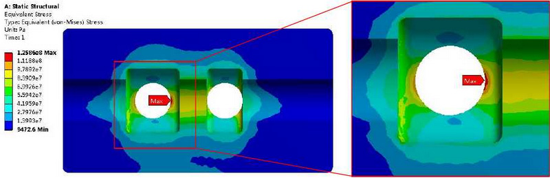
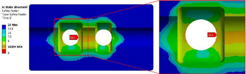
Fig. 2 is a cloud chart of the distribution of the fatigue safety factor of the ideal valve body under the pressure of 30MPa. It can be seen from the figure that the distribution of the minimum fatigue safety factor of the ideal valve body is the same as the distribution of the maximum stress of the valve body, in which the minimum fatigue safety factor is 2.0244.