
Because the deformation of blade sand casting is difficult to predict and control, and the deformation of blade sand casting depends on the stress field during blade solidification, it is necessary to numerically simulate the stress field during blade solidification and analyze the stress and deformation. Using the stress analysis module of ProCAST software, the stress field of the blade during solidification after improving the gating system is simulated, and the stress and deformation results during blade solidification are analyzed.
When the sand casting begins to solidify, the sand casting is in the condition of temperature change. At this time, if it is subject to external constraints or the mutual restraint between adjacent units, the deformation will not occur freely, so there will be stress, which is the so-called temperature stress, also known as thermal stress. This thermal stress will cause additional deformation due to the elasticity of sand castings. Therefore, in the case of variable temperature, the greater the stress of sand castings, the greater the deformation.
Figure 1 is the equivalent stress distribution diagram of blade sand casting at the time of complete solidification. It can be seen from the figure that the stress at the sharp corner of blade sand casting drain edge is the largest, about 350Mpa. The stress near the drain edge is greater than that at other positions, and the stress near the blade drain edge is about 70mpa-160mpa. This is because the blade is close to the drain edge and the thickness of the middle and lower part is very thin, so it is more sensitive to temperature, Affected by the release of latent heat of crystallization, the thermal stress here is greater than that at the thicker position of blade sand casting.
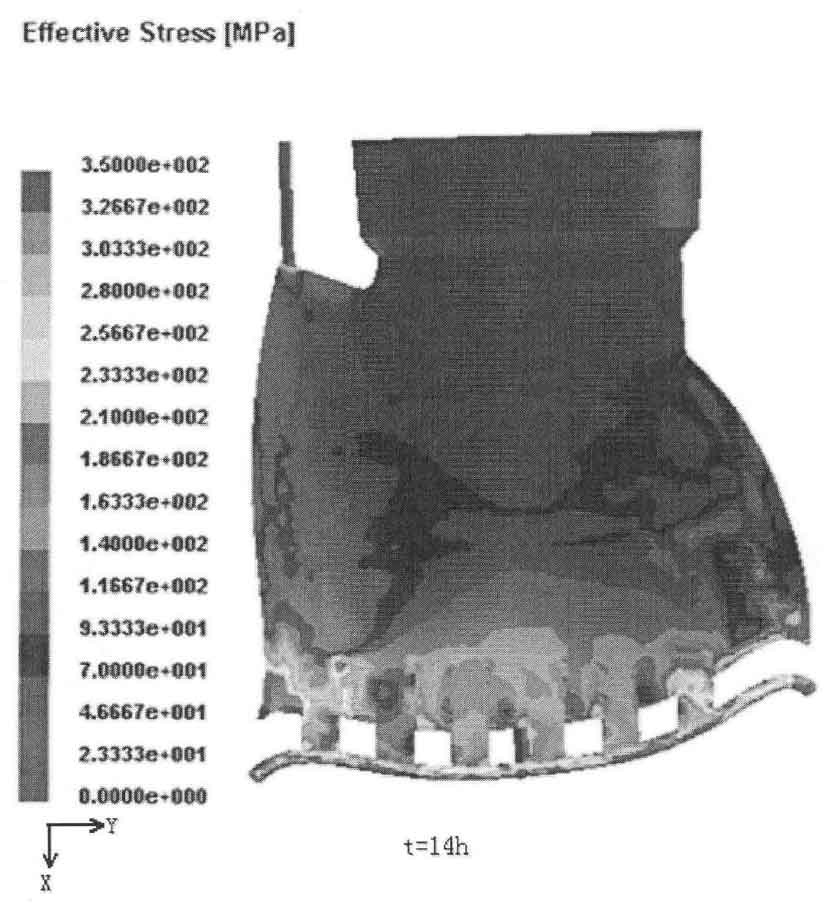
Figure 2-5 shows the simulation results of the deformation of blade sand casting. From Figure 2, it can be seen that in the X direction, the deformation at the sharp corner of blade discharge edge and water inlet edge is relatively large, the deformation at the sharp corner of blade discharge edge is about – 50mm, and the deformation at water inlet edge is about 25mm;
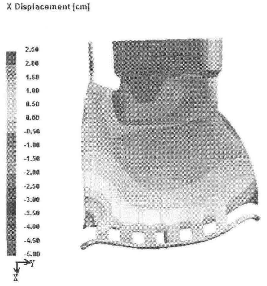
Figure 3 shows the distribution of deformation in Y direction. It can be seen from the figure that in Y direction, the sharp angle deformation of blade discharge edge is about 30mm and that at the lower ring is about – 25mm;
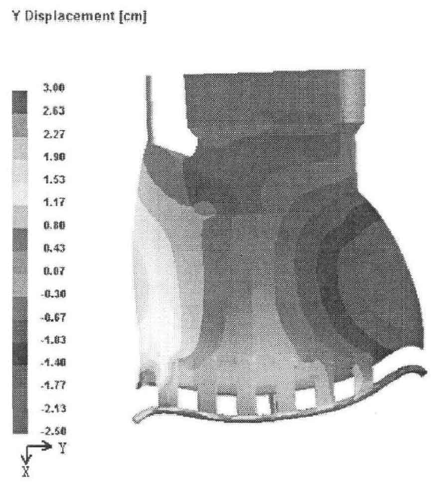
Figure 4 shows the distribution of deformation in the Z direction. It can be seen from the figure that in the Z direction, the deformation at the sharp corner of the discharge edge is about – 35mm and the deformation at the lower ring is about 20mm;
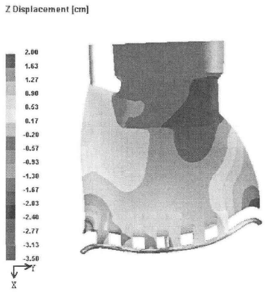
Figure 5 shows the distribution of total deformation of blade sand casting. It can be seen that the deformation at the sharp corner of the drain edge is the largest, about 50mm, followed by the lower ring edge, with the deformation between 20mm and 25mm.
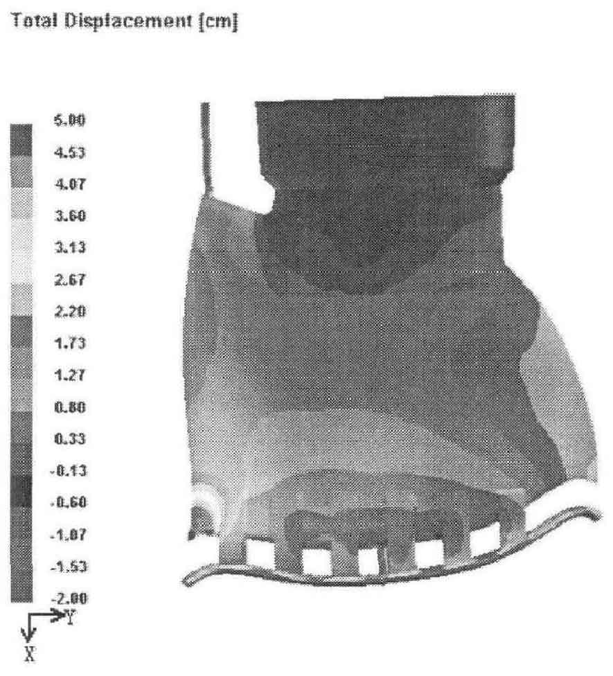
Based on the above analysis, it can be seen that the blade sand casting is easy to deform at the thin-walled positions such as the drain edge and the lower ring edge, especially the sharp corner of the drain edge, and the deformation is about – 20mm-50mm. According to the simulation results, when formulating the sand casting process, it is necessary to effectively compensate the position and amount of deformation of the blade sand casting due to the action of thermal stress in the solidification process, that is, add a certain amount of process reverse deformation in the position where the blade sand casting is easy to deform. When the casting process personnel manufacture the blade wood mold, the process reverse deformation value is added to the wood mold in advance to make the blade sand casting have enough reverse deformation, so as to offset the deformation caused by the solidification shrinkage of the blade sand casting.