
The imperative for reducing vehicular emissions is a dominant theme in modern automotive engineering, driven by stringent global environmental regulations. Statistics from the International Energy Agency indicate that the transportation sector contributes approximately 24% of global CO₂ emissions, with road vehicles being the largest single contributor. In economically developed regions, this proportion can be significantly higher. A fundamental strategy for curbing these emissions is vehicle lightweighting, which directly reduces the energy required for propulsion. As a core and heavy component of the internal combustion engine, the crankshaft presents a prime target for mass reduction initiatives. This analysis details a comprehensive structural lightweighting approach applied to a mature, high-volume production four-cylinder engine crankshaft manufactured from spheroidal graphite cast iron, specifically grade QT800-6. The goal was to achieve a mass reduction exceeding 10% without altering the material grade or the installation interface dimensions, thereby minimizing impact on the existing supply chain and engine assembly process.
The baseline crankshaft was a fully balanced design with eight counterweights, produced via the iron mold coated sand casting process. The material, QT800-6, offers a favorable combination of high tensile strength (≥800 MPa) and good ductility (elongation ≥6%), with a density of approximately 7.1 g/cm³. Its reinforcement process involved journal induction hardening followed by fillet rolling, a proven combination for enhancing fatigue performance. The primary specifications and initial mass are summarized below.
| Parameter | Value | Unit |
|---|---|---|
| Material | QT800-6 (Spheroidal Graphite Iron) | – |
| Main Journal Diameter | 85 | mm |
| Connecting Rod Journal Diameter | 70 | mm |
| Number of Counterweights | 8 | – |
| Crankpin Fillet Radius | Not Specified | mm |
| Raw Casting Mass | 50.6 | kg |
The lightweighting strategy was conceived as a multi-pronged structural modification, focusing on three key areas: reduction of counterweights, minimization of machining allowances, and the introduction of hollow journals.
1. Structural Modification Strategy
1.1 Counterweight Optimization and Mass Center Analysis
Analysis of production data revealed that the majority of unbalance correction during dynamic balancing was concentrated on the first and eighth counterweights. This indicated a potential redundancy in the fully balanced eight-counterweight design. A fundamental redesign to a non-fully balanced configuration with only four counterweights was proposed. The primary challenge was to ensure that the mass center of the new design remained congruent with its geometric center to prevent inherent unbalance. Using 3D CAD software, the mass properties of various configurations were simulated iteratively. The final design retained counterweights only on crank throws 1, 2, 3, and 4, and reduced the outer radius of these remaining counterweights from R93 mm to R91 mm. The software simulation confirmed that the offset between the mass center and geometric center was maintained within a critical threshold of 0.02 mm, satisfying the design prerequisite. The mass reduction from this change alone was significant.
Furthermore, the machining allowance on the side faces of the counterweights was reviewed. The original casting design included a draft angle resulting in a machining stock of up to 1.5 mm at the highest point. This was revised to a “zero allowance” design at the highest point, with stock only present on the parting line, achieving further mass savings directly from the raw casting.
1.2 Design and Implementation of Hollow Journals
Introducing hollow journals is a highly effective method for mass reduction. However, the design is constrained by the necessary wall thickness for structural integrity and the presence of lubricating oil holes. For this QT800-6 crankshaft, specific hollow geometries were engineered. The main journals were designed with a bore diameter of φ50 mm at the center, tapering to φ30 mm at the ends. The connecting rod journals featured a central bore of φ35 mm, tapering to φ25 mm at the ends. The transition zones were designed with smooth radii to avoid stress concentrations. Crucially, the bore profile was carefully modeled to avoid interference with the oblique oil holes drilled through the journals.
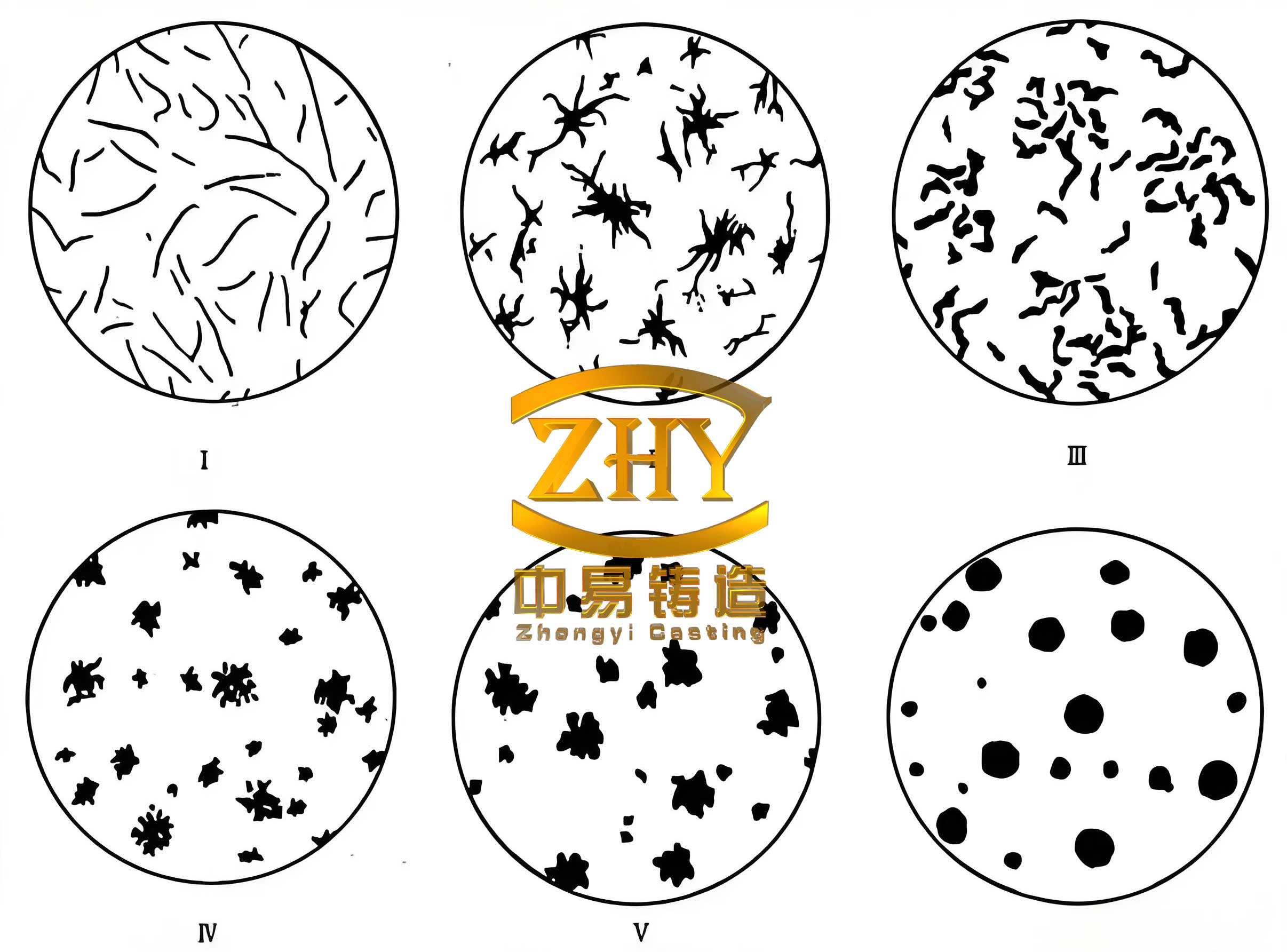
The microstructure of spheroidal graphite cast iron, as shown above, is key to its performance. The spherical graphite nodules act as crack arresters, providing good fatigue strength and ductility, which are essential for enduring the complex cyclic stresses in a lightweight, hollow crankshaft. Manufacturing these hollow structures required precision sand cores. Cores were produced using a high-strength, low-gas evolution resin sand system (e.g., epoxy-triethylamine), with a target immediate tensile strength exceeding 1.6 MPa. Anti-rotation features were incorporated into the core prints to prevent movement during casting, ensuring consistent wall thickness for the hollow journals.
1.3 Material and Process Consistency
While higher-grade spheroidal graphite cast iron such as QT1000-5 could offer potential for further lightweighting, it was not pursued in this project. The existing material and process combination (QT800-6 + hardening/rolling) had a mature and validated performance database. Switching materials would necessitate a full re-validation cycle encompassing fatigue, wear, and durability tests, requiring approximately one year—a timeframe incompatible with the project goals. Therefore, the focus remained on extracting maximum performance from the established QT800-6 grade through structural optimization.
2. Validation and Testing of the Lightweight Design
A batch of 200 crankshafts was manufactured according to the new design for comprehensive validation. The combined modifications resulted in a raw casting mass of 44.1 kg, achieving a mass reduction of 6.5 kg, which corresponds to a 12.84% decrease, successfully meeting the >10% target.
| Design Feature | Contribution to Mass Reduction | Notes |
|---|---|---|
| Reduction from 8 to 4 Counterweights | Primary Contribution | Radius reduction from R93 to R91 mm. |
| Zero Machining Allowance at Counterweight High Point | Secondary Contribution | Minimized excess material for machining. |
| Hollow Main and Connecting Rod Journals | Major Contribution | Optimized bore size avoiding oil holes. |
| Total Mass Reduction | 12.84% (50.6 kg → 44.1 kg) | – |
2.1 Dynamic Balance Validation
The dynamic balancing process was a critical verification step. The inherent unbalance \( U \) of a rotor is given by \( U = m \cdot r \), where \( m \) is the unbalanced mass and \( r \) is its radius from the axis of rotation. The design target for residual unbalance after correction was 20 g·cm. The production data from the 200 samples was analyzed:
- Number of crankshafts with initial unbalance ≤ 300 g·cm: 165 (82.5%).
- All 200 crankshafts were successfully balanced to within the 20 g·cm specification after corrective machining.
While the rate of crankshafts with lower initial unbalance was slightly less favorable compared to the original 8-counterweight design (86%), the results were within an acceptable operational range, requiring only marginally more correction effort.
2.2 Torsional Vibration Analysis
Removing four counterweights alters the torsional stiffness and inertia distribution of the crankshaft, potentially affecting the torsional vibration characteristics of the engine’s rotating assembly. Bench testing was conducted in accordance with the standard method for measurement and evaluation (analogous to GB/T 15371). The torsional vibration amplitude \( \theta_i \) for each significant engine order (harmonic) \( i \) was measured across the engine speed range. The critical design limit was set at \( \theta_{\text{limit}} = 0.2^\circ \).
| Engine Order (Harmonic) | Maximum Amplitude, \( \theta_i \) (°) | Speed at Maximum (rpm) |
|---|---|---|
| 2 | 0.072 | 2948 |
| 4 | 0.037 | 2900 |
| 4.5 | 0.026 | 2813 |
| 5.5 | 0.036 | 2855 |
| 6 | 0.044 | 2800 |
| 6.5 | 0.020 | 2760 |
| 8 | 0.076 | 2699 |
The single-order maximum amplitude of 0.076° was observed for the 8th order at 2699 rpm. Crucially, all measured amplitudes satisfied the condition \( \theta_i < \theta_{\text{limit}} \), confirming that the lightweighted crankshaft did not induce excessive torsional vibrations and was acceptable for the engine’s operational envelope.
2.3 Bending Fatigue Strength Validation
The most critical mechanical validation was the bending fatigue strength test, as hollow journals can influence stress concentrations. Testing was performed on a resonant fatigue testing machine (e.g., DXP-200 type) under fully reversed bending (stress ratio R = -1). The fatigue limit bending moment \( M_{\text{lim}} \) was determined using the staircase (up-and-down) method with a run-out criterion of \( 10^7 \) cycles. The safety factor \( n \) is defined as the ratio of the material’s endurance limit (derived from \( M_{\text{lim}} \)) to the maximum working stress (calculated from the nominal operating bending moment \( M_{\text{op}} \)):
$$ n = \frac{\sigma_{\text{endurance}}}{\sigma_{\text{working}}} \propto \frac{M_{\text{lim}}}{M_{\text{op}}} $$
The requirement for spheroidal graphite cast iron crankshafts in this application was \( n \geq 1.8 \). The test matrix and results are summarized below. Outliers were identified and excluded according to the staircase method protocol before calculating the fatigue limit.
| Specimen ID | Bending Moment (N·m) | Cycles to Failure / Status | Result |
|---|---|---|---|
| 1-1 | 3400 | 10,521,000 | Failed |
| 1-4 | 3300 | 100,000,000 | Run-out (Pass) |
| 2-1 | 3400 | 3,486,000 | Failed |
| 2-4 | 3300 | 100,000,000 | Run-out (Pass) |
| 3-4 | 3400 | 13,274,000 | Failed |
| 3-1 | 3300 | 4,742,000 | Failed |
| 4-4 | 3300 | 100,000,000 | Run-out (Pass) |
| 4-1 | 3400 | 2,022,000 | Failed |
| 5-4 | 3300 | 100,000,000 | Run-out (Pass) |
| 5-1 | 3400 | 2,673,000 | Failed |
| 6-4 | 3300 | 100,000,000 | Run-out (Pass) |
| 6-1 | 3400 | 6,182,000 | Failed |
| 7-4 | 3300 | 45,750,000 | Failed |
| 7-2 | 3300 | 100,000,000 | Run-out (Pass) |
| 8-1 | 3400 | 1,038,000 | Failed |
| 8-3 | 3300 | 2,077,000 | Failed |
| 8-4 | 3300 | 100,000,000 | Run-out (Pass) |
| 8-2 | 3400 | 8,457,000 | Failed |
Statistical analysis of the valid data points from the staircase test yielded a calculated safety factor of \( n = 1.87 \). This conclusively demonstrated that the lightweight design, incorporating hollow journals in spheroidal graphite cast iron, met and exceeded the minimum safety requirement of 1.8.
3. Conclusion and Discussion
This project successfully demonstrated a feasible and effective structural lightweighting pathway for a high-volume production crankshaft made from spheroidal graphite cast iron QT800-6. A 12.84% mass reduction was achieved through a synergistic combination of counterweight optimization and the introduction of carefully designed hollow journals. The modified crankshaft passed all critical validation tests:
- Dynamic Balance: All parts were balanceable to specification, with acceptable process efficiency.
- Torsional Vibration: Amplitudes for all engine orders remained well below the permissible limit of 0.2°.
- Bending Fatigue Safety: A safety factor of 1.87 was validated, ensuring structural integrity under engine operating loads.
The success of this approach highlights the significant potential for mass optimization inherent in mature component designs through detailed structural analysis and targeted modifications. It is important to note that implementing hollow journals introduces additional manufacturing considerations, such as the need for high-integrity sand cores and stringent cleaning processes to remove core sand residues, which may slightly increase unit cost. However, the benefits in reduced inertia and improved engine efficiency often outweigh these costs.
Future lightweighting explorations for spheroidal graphite cast iron crankshafts could involve topology optimization for material distribution, further refinement of hollow journal shapes using finite element analysis, and the adoption of even higher-strength ductile iron grades like QT1000-5, coupled with advanced surface enhancement techniques, to push the boundaries of performance and mass reduction even further.