
In my experience as a casting engineer, producing high-quality thick and complex spheroidal graphite iron castings has always been a significant challenge due to the inherent shrinkage porosity and cavity formation tendencies. The unique solidification characteristics of spheroidal graphite iron, involving wide eutectic temperature ranges and mushy solidification, demand precise process control. This article delves into the intricacies of the sand-coating iron mold technology, leveraging advanced simulation analysis and optimized riser design to achieve defect-free castings. Through extensive analysis, I will explore the fundamental principles, compare various molding processes, and present a detailed case study, emphasizing the critical role of simulation in modern foundry practices.
The solidification behavior of spheroidal graphite iron is markedly different from other alloys, primarily due to graphite nodule formation within an austenite shell, which slows carbon diffusion and extends the eutectic transformation over a broad temperature range. This results in a pasty or mushy solidification mode, where solid and liquid phases coexist across wide sections, complicating feeding and promoting shrinkage defects. The volumetric changes during cooling and solidification are complex, involving both contraction and expansion phases. Theoretical and experimental studies have shown that the net volume change can vary, influenced by metallurgical and process factors. For instance, the carbon equivalent significantly impacts expansion forces, with maximum expansion occurring near the eutectic point. Other factors like magnesium content, rare earth additions, inoculation, modulus of the casting, mold rigidity, and pouring temperature all interplay to affect the final shrinkage behavior. The equation for volumetric change during solidification can be approximated as:
$$ \Delta V = V_{\text{liquid contraction}} + V_{\text{solidification contraction}} – V_{\text{graphite expansion}} $$
where $V_{\text{graphite expansion}}$ is the expansion due to graphite precipitation, which in spheroidal graphite iron can partially offset shrinkage if properly harnessed. However, premature graphite expansion during liquid cooling can expel metal from the mold cavity, hindering feeding and leading to porosity. The mold cavity dimensions also change during pouring and cooling, influenced by mold wall movement. In sand molds, especially green sand, cavity expansion occurs continuously until solidification ends, exacerbating shrinkage tendencies. In contrast, iron molds with sand coating exhibit minimal expansion after pouring, maintaining cavity stability and supporting self-feeding via graphite expansion. This underscores the importance of mold rigidity in controlling shrinkage defects in spheroidal graphite iron castings.
| Process | Advantages | Disadvantages | Suitability for Thick Complex Castings |
|---|---|---|---|
| Resin Sand (Cold-Cure) | High strength, good thermal stability, minimal mold wall movement | High cost, environmental concerns, risk of gas defects, low production efficiency | Moderate (for single-piece, large castings with chills) |
| Green Sand | Low cost, short cycle, high productivity | Low rigidity, cavity expansion, high shrinkage tendency, low yield | Poor (requires large risers and chills) |
| Sand-Coating Iron Mold | High rigidity, fast cooling, dimensional accuracy, high yield, suitable for automation | Initial tooling cost, limited to certain geometries | Excellent (enables near-net-shape casting with minimal risers) |
The sand-coating iron mold process involves coating a metal mold with a thin layer of resin-coated sand, typically 6-15 mm thick, creating a rigid mold assembly. This combines the rapid cooling of metal molds with the flexibility of sand cores, making it ideal for spheroidal graphite iron. The high rigidity resists mold wall movement, allowing the graphite expansion to be utilized for self-feeding, while the thin sand layer prevents chilling defects like white iron formation. The process parameters, such as sand layer thickness, are optimized based on simulation results. For example, in thick sections, a thinner sand layer (e.g., 6-8 mm) enhances cooling, whereas in runners, a thicker layer (12-15 mm) ensures proper filling. The sand-to-metal ratio can be as low as 0.2, reducing material waste and cost. Key advantages include improved environmental conditions due to reduced sand usage, automated production lines utilizing residual heat for sand curing, and the ability to produce as-cast spheroidal graphite iron without heat treatment for certain grades.
Simulation analysis technology has revolutionized casting process design by visualizing filling, solidification, and cooling, enabling defect prediction and optimization without physical trials. For spheroidal graphite iron, simulations help preempt shrinkage porosity by analyzing temperature gradients, solidification sequences, and feeding paths. Using software like Magma or AnyCasting, I can model volumetric changes and identify isolated liquid regions that may lead to shrinkage. The governing equations for heat transfer and fluid flow are solved numerically, such as the energy equation:
$$ \rho C_p \frac{\partial T}{\partial t} = \nabla \cdot (k \nabla T) + Q_{\text{latent}} $$
where $\rho$ is density, $C_p$ is specific heat, $T$ is temperature, $t$ is time, $k$ is thermal conductivity, and $Q_{\text{latent}}$ is the latent heat release during solidification of spheroidal graphite iron. By adjusting riser sizes, positions, and chill placements in the virtual model, I can achieve directional solidification towards risers, ensuring sound castings. Simulation also aids in selecting optimal pouring temperatures and rates, minimizing turbulence and oxidation. In one instance, for a thick-walled spheroidal graphite iron component, simulation revealed that a top-gating system with exothermic risers provided better feeding than a tangential gating system with chills, leading to a redesign that improved yield from 83.5% to 93.8%.
A typical case study involves a thick, complex wheel-shaped spheroidal graphite iron casting weighing 134 kg, with material specification QT600-3 requiring tensile strength over 750 MPa and elongation above 3%. The casting had varying wall thicknesses from 15 mm to 85 mm, demanding precise control to avoid shrinkage porosity and ensure hardness uniformity of 240-270 HB. Two process schemes were designed and simulated. Scheme 1 used tangential gating on the flange with chills and a conventional riser, aiming for balanced solidification via graphite expansion. Simulation indicated isolated liquid zones prone to shrinkage, as shown by a porosity prediction model:
$$ P_{\text{porosity}} = f(\Delta T, G, \dot{T}) $$
where $P_{\text{porosity}}$ is the porosity probability, $\Delta T$ is the solidification range, $G$ is the temperature gradient, and $\dot{T}$ is the cooling rate. For spheroidal graphite iron, a wide $\Delta T$ increases $P_{\text{porosity}}$ if feeding is inadequate. Scheme 2 employed a top-gating system with an exothermic riser serving as both sprue and feeder, plus three additional exothermic risers near hot spots. Simulation confirmed open feeding channels until solidification completion, with riser modulus calculations ensuring sufficient feed metal. The modulus method for riser sizing is given by:
$$ M_{\text{riser}} = k \cdot M_{\text{casting}} $$
where $M$ is modulus (volume-to-surface area ratio) and $k$ is a factor typically 1.2 for spheroidal graphite iron. Exothermic risers, with compositions generating heat through reactions like $2Al + Fe_2O_3 \rightarrow 2Fe + Al_2O_3 + \text{heat}$, extend liquid longevity, achieving feeding efficiencies of 30-35%. Production validation involved melting in medium-frequency induction furnaces using steel scrap and returns, with pretreatment, spheroidization using KM-071 agent, and inoculation with KY-C and KY-D inoculants. The chemical composition was controlled within ranges critical for spheroidal graphite iron quality, as summarized below:
| Element | Range | Influence on Spheroidal Graphite Iron |
|---|---|---|
| C | 3.4-3.9 | Promotes graphite formation, affects expansion |
| Si | 2.0-2.4 | Enhances fluidity, ferrite formation |
| Mn | 0.1-0.6 | Increases strength, but may segregate |
| P | ≤0.05 | Reduces ductility if high |
| S | ≤0.02 | Low levels crucial for effective spheroidization |
| Cu | 0.2-0.6 | Improves hardness and pearlite content | Mgres | 0.035-0.055 | Essential for graphite nodularization |
| RE | 0.02-0.04 | Aids nodularization, counteracts impurities |
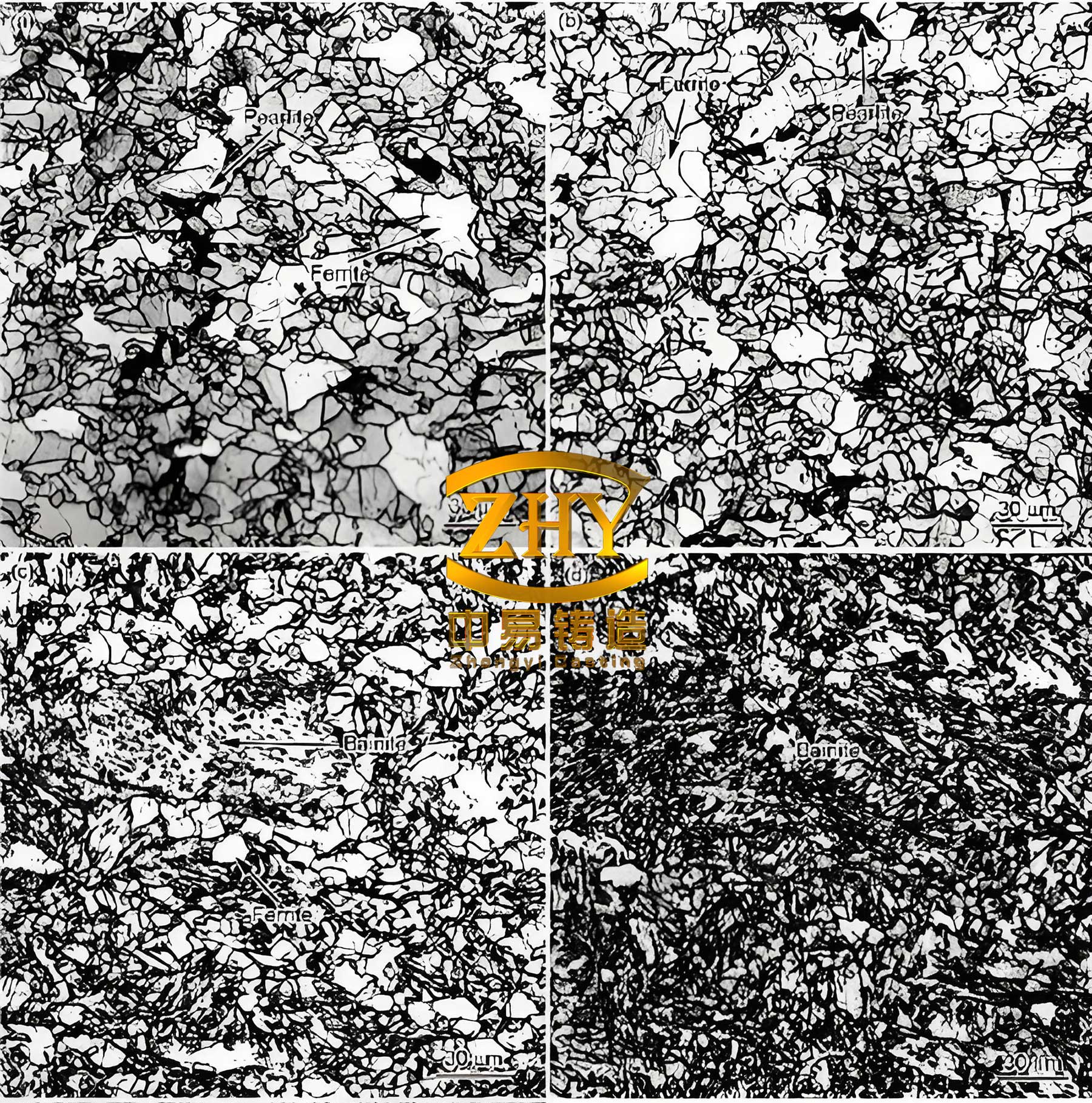
Melting was conducted at 1520-1580°C, with pouring at 1340-1420°C, and the total processing time kept under 8 minutes to prevent fading. Inoculation was performed in multiple stages: 0.5-0.9% KY-C in the ladle and 0.1-0.2% KY-D during pouring, ensuring fine graphite nodules and minimizing undercooling. The sand-coating iron mold was prepared with a 8-10 mm sand layer on most surfaces, 6-8 mm at rib junctions, and 12-15 mm in runners, based on simulation outputs. Venting holes were incorporated to avoid gas defects. Scheme 1 production resulted in shrinkage porosity in thick sections upon dissection, attributed to premature graphite expansion expelling metal and insufficient feeding despite chills. Scheme 2, however, yielded sound castings with no defects visible in ultrasonic and dye-penetrant tests. Mechanical properties from the casting body exceeded requirements: tensile strength 858 MPa, elongation 5.2%, and hardness 242-255 HB. Microstructure analysis showed over 90% nodularity, graphite size grade 6-7, and pearlite content >85%, meeting specifications for spheroidal graphite iron components.
The success of Scheme 2 highlights the synergy between simulation, exothermic risers, and sand-coating iron mold technology. For spheroidal graphite iron, this combination leverages mold rigidity to harness graphite expansion while providing external feeding where needed. The feeding efficiency of exothermic risers can be modeled as:
$$ \eta_{\text{riser}} = \frac{V_{\text{feeding}}}{V_{\text{riser}}} \times 100\% $$
where $\eta_{\text{riser}}$ is typically 30-35% for exothermic types, compared to 10-15% for conventional sand risers. In practice, I have found that optimizing riser neck dimensions is critical to maintain open channels; too small a neck solidifies early, isolating the hot spot. The neck modulus should satisfy:
$$ M_{\text{neck}} \geq 0.67 \cdot M_{\text{hot spot}} $$
for spheroidal graphite iron. Additionally, the pouring system design influences temperature distribution; top-gating with filters, as in Scheme 2, ensures clean metal entry and thermal uniformity, reducing turbulence-related defects. The sand-coating process also minimizes mold gas generation, as the thin resin-coated sand layer decomposes with less gas evolution compared to bulk sand molds. This is quantified by the gas evolution rate:
$$ \dot{G} = A e^{-E/RT} $$
where $\dot{G}$ is gas evolution rate, $A$ is a pre-exponential factor, $E$ is activation energy, $R$ is gas constant, and $T$ is temperature. Lower sand volume reduces $\dot{G}$, decreasing gas defect risks in spheroidal graphite iron castings.
In conclusion, producing thick and complex spheroidal graphite iron castings demands a holistic approach integrating metallurgy, process design, and advanced simulation. The sand-coating iron mold technology stands out for its high rigidity, rapid cooling, and suitability for automation, enabling high-yield production of quality spheroidal graphite iron components. While self-feeding via graphite expansion is beneficial, external feeding with exothermic risers is often necessary for uneven sections, as demonstrated in the case study. Simulation tools are indispensable for predicting shrinkage and optimizing riser placements, reducing trial runs and costs. Future advancements may focus on real-time monitoring and adaptive control during pouring to further enhance spheroidal graphite iron casting quality. Through continued innovation, the foundry industry can achieve even greater efficiency and reliability in manufacturing these critical components.